
 WhatsApp: +86 16626708626
 Email:
  Phone: +86 16626708626
Description
3. Key Technical Specifications
- Rated Current: 300 A continuous at 600 VDC max
- Poles: 3 (main contacts)
- Coil Voltage: 250–300 VDC (GXA003XF code)
- Coil Power: Approximately 25–35 W continuous (pull-in higher)
- Contact Material: Silver alloy with arc chutes and magnetic blowout
- Interrupting Capacity: Up to 10 kA at 600 VDC (depends on application)
- Mechanical Life: 1,000,000 operations (no load)
- Electrical Life: 100,000 operations at rated load
- Operating Temperature: –20 °C to +55 °C
- Mounting: Panel or base mount with 4 mounting holes
- Dimensions (approx.): 12.7 cm H × 20.3 cm W × 15.2 cm D
- Weight (approx.): 9.1 kg (20 lb)
- Auxiliary Contacts: None in this exact configuration (XF code)
- Enclosure: Open style, IP00
- Standards: Meets NEMA ICS and typical mining/industrial DC duty

- DS303A3A01GXA003XF
4. Product Introduction
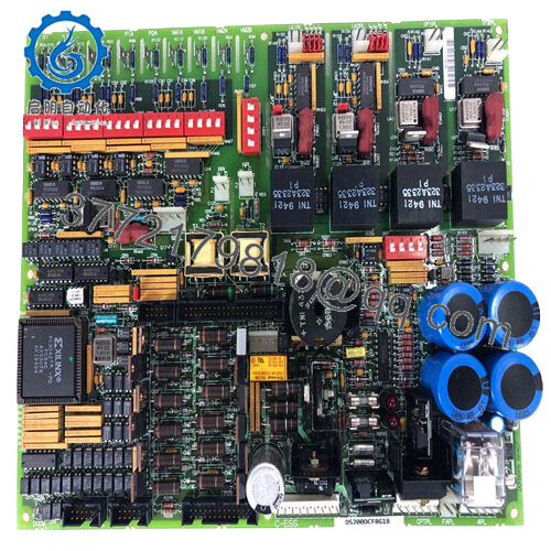
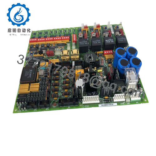
The GE DS303A3A01GXA003XF is a 300 A, 3-pole DC contactor from the DS303 series. Plants use it to switch and protect high-current DC loads such as mill motors, crane hoists, mining draglines, and electrolytic cell lines in metal processing and heavy industry.
This version carries the 250–300 VDC coil, magnetic arc blowout coils for reliable DC interruption, and the heavy-duty construction typical of GE’s older industrial line. Technicians still specify it when exact form, fit, and function match existing panels because the DS303 footprint and terminal layout have remained consistent for decades, simplifying direct replacement without rewiring the bus bars or control circuits.
5. Installation & Configuration Guide
Stage 1: Pre-Installation Preparation (10–15 minutes) ⚠️ Safety First: Lock out and tag out the entire DC bus. Confirm zero voltage on both line and load sides with a high-voltage rated multimeter. Discharge any capacitors in the system and verify the contactor is in the open position. Tools Required: Grounded ESD wrist strap (for coil circuit), 3/8-inch socket set or wrench, torque wrench, wire labels, multimeter, camera. Data Backup: Photograph the existing contactor from all angles showing coil wiring, main bus connections, and any interlocks. Record coil resistance and note any auxiliary wiring even if this model has none.
Stage 2: Removing the Old Contactor (5–10 minutes)
- Confirm power is off and locked out.
- Label and disconnect the coil wires first (usually smaller gauge).
- Remove the main power bus bars or cables from the line and load terminals. Support heavy cables to prevent strain.
- Unbolt the four mounting feet from the panel or frame.
- Lift the contactor straight out, watching for any attached arc chute pieces. ⚠️ Note: Keep the old unit as a physical reference until the new one passes load testing.
Stage 3: Installing the New Module (10–15 minutes)
- Verify the new contactor is exactly DS303A3A01GXA003XF and shows no shipping damage.
- Set the contactor in place and bolt it down using the original mounting pattern and proper torque.
- Reconnect the main power terminals first, then the coil circuit. Match polarity on the coil exactly as photographed.
- Inspect arc chutes for proper seating and blowout coil alignment. Self-Checklist: [ ] Mounting bolts torqued, [ ] All connections tight and polarity correct, [ ] Arc chutes in place, [ ] No exposed bus gaps.
Stage 4: Power-On & Testing (15–25 minutes) Pre-Power Check: Measure coil resistance (should be in the 200–400 Ω range for this voltage). Confirm no shorts between poles or to ground. Power-On Steps:
- Restore control power only and energize the coil. Listen for a clean clunk and verify contacts close fully.
- Measure coil voltage at the terminals while energized.
- With main DC bus live but load isolated, cycle the contactor several times and check for excessive arcing or noise.
- Reconnect the load and perform a loaded test at reduced current if possible, then at full operating current. Monitor temperature rise on contacts and coil after 30 minutes.
- Verify auxiliary signals (if added externally) and interlocks function correctly. ⚠️ Troubleshooting Note: If the contactor chatters or fails to close, check coil voltage drop and polarity. If it welds on opening, inspect blowout coils and arc chutes for damage or misalignment. High contact temperature usually indicates loose bus connections.
Total typical replacement time for a trained technician: 45–60 minutes.
6. Frequently Asked Questions (FAQ)
Can this contactor be serviced or replaced while the DC bus is live? No. The DS303 is an open-style contactor with exposed live parts. Attempting hot replacement risks severe arc flash, equipment damage, and personnel injury. Always de-energize the bus first.
Is the DS303A3A01GXA003XF obsolete, and are these units new? Yes, the DS303 series has been obsolete for many years. These are new surplus units — genuine GE stock that was never installed in the field. Each unit receives full mechanical inspection, coil resistance and insulation testing, and a 24-hour burn-in cycle before shipment. Test data is available on request.
What is the current OEM direct replacement? GE no longer manufactures an exact drop-in. Many users migrate to modern equivalents such as the Eaton or ABB DC contactors with similar ratings, but this usually requires adapter plates or bus work changes. A full engineering review of duty cycle and interrupting requirements is mandatory before upgrading.
Does this model include auxiliary contacts? The specific code ending in XF indicates no built-in auxiliary contacts. Most installations add separate auxiliary relays or use external limit switches if status feedback is required. Confirm your original schematic before ordering.
Why is the price significantly lower than historical GE list price? Because these are new surplus rather than current production. We source directly from decommissioned or excess OEM inventory, perform complete incoming and functional testing on actual DC test benches, and pass on the savings. All units carry a 1-year functional warranty from shipment date.
How critical is coil polarity on this 250–300 VDC model? Very important. Incorrect polarity can reduce holding force or cause overheating. Always match the coil wiring exactly as documented on the old unit. The magnetic blowout system also depends on correct current direction for proper arc extinction.
What maintenance is typically required on a DS303 contactor after installation? Inspect contact wear and arc chute condition every 6–12 months depending on operation frequency. Clean blowout coils and replace any pitted contacts. The unit has no electronic components, so failures are almost always mechanical or from contamination in harsh environments. Keep spare arc chutes and contact kits on hand for critical applications.


