
 WhatsApp: +86 16626708626
 Email:
  Phone: +86 16626708626
Description
3. Key Technical Specifications
| Parameter | Value |
|---|---|
| Model | DS3800DCCA |
| Brand | GE (General Electric) |
| Series | Mark IV Speedtronic |
| Board Type | Communication Coprocessor / Data Concentrator |
| Power Supply | +5V DC from backplane |
| Current Draw | 1.8A typical on +5V rail |
| Processor | 16-bit (Intel 80186 or equivalent custom GE ASIC) |
| Memory | 512KB RAM, 512KB Flash/EPROM (firmware) |
| Communication Ports | 4 x serial ports (software configurable) |
| Port 1 | RS-232 (DB9 male) |
| Port 2 | RS-232 or RS-422 (jumper selectable) |
| Port 3 | RS-485 (2-wire or 4-wire) |
| Port 4 | RS-232 (dedicated for printer or maintenance terminal) |
| Baud Rates | 300 to 115,200 baud (software selectable) |
| Protocols | GE proprietary I/O bus, Modbus RTU (certain firmware versions), DNP3 (optional) |
| Backplane Interface | VME-style 96-pin DIN (P1, P2) |
| Status LEDs | 6 x LEDs (Power, Run, Fault, Port 1-3 Activity) |
| DIP Switches | 8-position (node address, boot options, watchdog) |
| Operating Temp | 0 to +50°C (32 to 122°F) |
| Storage Temp | -40 to +85°C (-40 to 185°F) |
| Humidity | 5% to 95% non-condensing |
| Dimensions | 9.5 x 6.5 x 1.0 inches (approx) |
| Connectors | 1 x 96-pin backplane, 4 x serial ports (front panel) |
| GE Part Family | DS3800 (Mark IV) |
| Firmware | Version marked on EPROM label (verify compatibility) |
4. Product Introduction
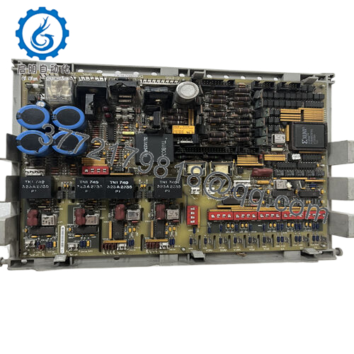
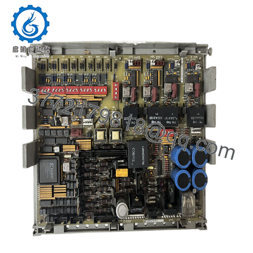
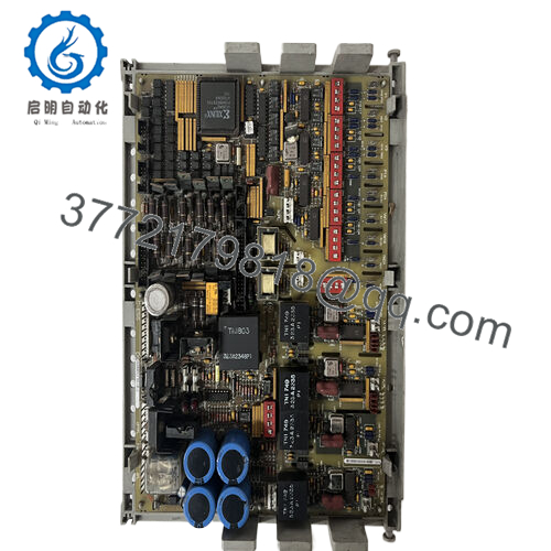
The GE DS3800DCCA is the DCCA communication coprocessor board for the Mark IV Speedtronic turbine control system. This board handles serial communication between the Mark IV rack and external devices — operator workstations, remote I/O, PLCs, DCS systems, printers, and maintenance terminals. You’ll find it in gas and steam turbine applications where data needs to move in and out of the control system.
The DCCA board offloads communication tasks from the main processor (CPC/PPC). It scans remote I/O racks over RS-485, talks to plant-wide DCS over Modbus RTU, and drives operator displays. The board has four configurable serial ports supporting RS-232, RS-422, and RS-485. Without a functional DCCA, the main processor loses external communication — no operator screen, no remote data, no historian logging. The turbine may still run, but you’re flying blind.

- DS3800DCCA
5. Troubleshooting Quick Reference
| Symptom | Possible Cause | Relevance to this Part | Quick Check Method | Recommendation |
|---|---|---|---|---|
| No LEDs lit on DCCA | Backplane +5V missing or board not seated | ❌ Low (backplane issue) | Measure +5V on backplane pins. Reseat board firmly. | Check rack power supply (NPSR). Replace DCCA only if +5V present but board dead. |
| Run LED off, Fault LED on steady | Firmware checksum failure or hardware fault | ✅ High | Read Mark IV diagnostic display. Look for DCCA fault codes (typically 100-109 range). | Cycle rack power. If fault persists, replace board. EPROM may need reprogramming. |
| Fault LED flashing (1 Hz) | Communication loss with main processor | ✅ High | Check backplane connections. Verify main processor (CPC/PPC) is running and out of reset. | Reseat both boards. Replace DCCA if communication fails to recover. |
| Port 1 (RS-232) no communication | Driver chip failed or configuration mismatch | ✅ High | Loopback test: Short pins 2 and 3 on DB9. Send data from terminal — should echo. | Replace DCCA. Driver chips (MAX232 or 1488/1489) are not field-replaceable on this board. |
| Port 2/3 (RS-422/485) no data | Termination resistor missing or wiring error | ✅ Medium | Check termination (120 ohm resistor at both ends of RS-485 bus). Verify A/B polarity. | Add termination resistors. Swap A/B if no data. Replace DCCA if loopback test fails. |
| Intermittent communication, data drops | Ground loop or noise on serial cable | ✅ Medium | Measure voltage between signal ground and earth ground. Should be <1V AC. | Use isolated converters or fiber optic. Replace DCCA if RS-485 driver is failing. |
| DCCA communicates but resets randomly | Watchdog timer expired or power supply dip | ✅ High | Monitor +5V with oscilloscope. Look for drops below 4.75V. | Replace rack power supply first. If issue persists, replace DCCA. |
| Operator workstation shows “Comm Lost” | DCCA not responding or cable failed | ✅ High | Check DCCA LEDs. If Run LED is on, cable issue. If Fault LED on, board issue. | Replace cable first. If cable good, replace DCCA. |
| All ports dead but Run LED on | Internal bus failure or clock oscillator failed | ✅ High | Measure clock output on test point (if marked). Should show appropriate frequency. | Replace board. This failure is not field-repairable. |
Tech Note: The DCCA uses electrolytic capacitors on its power input section. After 20+ years, these caps dry out, causing the +5V rail to ripple. The board may work for hours then reset. If you see random resets, suspect capacitors first.
6. Frequently Asked Questions (FAQ)
Q: Is the DS3800DCCA a direct replacement for older DCCA revisions like DCCAA or DCCAB?
A: Yes, with a firmware compatibility check. The base DCCA (no suffix letter) is the original design. Later revisions (DCCAA, DCCAB) added minor hardware updates. This DCCA board is backward compatible with all Mark IV racks. However, the firmware version matters. If your system expects a specific Modbus or DNP3 implementation, verify the EPROM version on your existing board. We can match firmware versions from our inventory — just provide the EPROM label text.
Q: Can I use the DCCA to connect my Mark IV to a modern PLC over Modbus TCP?
A: Not directly. The DCCA has serial ports only (RS-232/422/485). It supports Modbus RTU (serial), not Modbus TCP (Ethernet). To connect to a modern PLC over Ethernet, you need a serial-to-Ethernet converter (e.g., Moxa or Digi device server). The DCCA sees the converter as a serial device. We can recommend specific converters that work with Mark IV timing requirements.
Q: How do I configure the DCCA’s serial ports?
A: Configuration is done through the Mark IV maintenance terminal or Toolbox (depending on system age). Parameters per port:
- Protocol (GE proprietary, Modbus RTU, DNP3, printer)
- Baud rate (300 to 115,200)
- Data bits (7 or 8)
- Parity (none, even, odd)
- Stop bits (1 or 2)
Write down your existing configuration before replacing the board. The new board ships with factory defaults. We can preset the DIP switches and EPROM configuration to match your application — just provide your current settings.
Q: Can I hot-swap the DCCA while the Mark IV rack is powered?
A: No. The Mark IV backplane has live +5V and communication signals. Hot-swapping can damage the backplane transceivers on both the DCCA and the main processor. Procedure: Power down the entire rack (both AC and DC inputs to the NPSR). Wait 30 seconds. Then swap. Then power up.
Q: Why is my DCCA showing a fault but my turbine still runs?
A: The DCCA is not required for basic turbine control — the main processor (CPC/PPC) can run the turbine alone. The DCCA only handles external communication. If it fails, the turbine keeps running, but you lose operator interface, remote I/O, and data logging. This is dangerous because you can’t monitor the turbine. Replace the DCCA at the next scheduled outage. Do not run indefinitely without communication.
Q: What’s the difference between DCCA and other Mark IV communication boards?
A: Quick reference:
- DCCA (DS3800DCCA): Serial communication coprocessor (RS-232/422/485). General purpose.
- DCCB (DS3800DCCB): Similar to DCCA but with fiber optic ports.
- DCPC (DS3800DCPC): Printer/display controller (dedicated).
- DCXX (DS3800DCXX): Custom protocol board for specific customer applications.
The DCCA is the standard communication board for most Mark IV installations. If you have fiber optic links to remote racks, you need DCCB instead.
Q: How do I bench test the DCCA without a Mark IV rack?
A: You need a +5V power supply (3A minimum) and a serial terminal. Procedure:
- Apply +5V to backplane pins (refer to pinout document).
- Board LEDs should light (Power OK, Run — Fault may flash briefly then go off).
- Connect a PC serial terminal to Port 1 (9600 baud, 8/N/1).
- Power cycle the board while watching the terminal. You should see a boot message (e.g., “DCCA v3.2”).
- If no boot message, try Port 4 (maintenance port).
Simpler approach: Install in a known-good rack. We can provide a test report from our Mark IV test rack instead.
Q: My DCCA communicates with my operator workstation but not with my plant DCS. Why?
A: Two likely issues:
- Protocol mismatch — The DCCA may be running GE proprietary protocol on that port. Your DCS expects Modbus RTU. Check the port configuration in the Mark IV software.
- Ground loop — RS-485 can have ground potential differences between the turbine panel and the DCS panel. Measure voltage between signal grounds. If >2V AC, use isolated converters.
We can help debug your specific configuration. Send us your port configuration and DCS make/model.
Q: What’s your testing process for this board?
A: We test every DS3800DCCA on a live Mark IV test rack with a known-good main processor. Test sequence:
- Visual inspection for corrosion, rework, or damage
- EPROM verification (checksum and version match)
- Power-on test (+5V current draw, LED sequence)
- Backplane communication test (processor sees DCCA and exchanges data)
- Serial port test: All 4 ports, loopback at 9600, 19200, and 115200 baud
- Protocol test: Modbus RTU slave emulation (read/write holding registers)
- 24-hour burn-in with communication stress test (continuous Modbus polling)
Test report with port configuration and firmware version available upon request.
Q: My plant has a Mark IV with two DCCA boards in one rack. Can I replace only one?
A: Yes, if they are configured as independent communication channels (e.g., one for operator workstation, one for DCS). But verify they are not configured as a redundant pair. Redundant DCCA boards require identical firmware and matched hardware revisions. Replace both if running in redundancy. Check your system documentation or send us photos of the rack configuration — we’ll advise.


