
 WhatsApp: +86 16626708626
 Email:
  Phone: +86 16626708626
Description
3. Key Technical Specifications
| Parameter | Value |
|---|---|
| Product Type | Voltage / Generator Regulator Board |
| Series | GE Mark IV Speedtronic |
| Function | Voltage regulation & control processing |
| Processor | Microprocessor-based control |
| Memory | EPROM modules (up to 14 sockets) |
| Connectivity | 2 × 34-pin ribbon cables |
| Connectors | Ribbon + single-pin connectors |
| Configuration | 17 onboard jumpers |
| Power Supply | Backplane-fed |
| Dimensions | ~263 × 58 × 28 mm |
| Weight | ~0.4–0.9 kg |
| Application | Turbine control / generator regulation |
4. Product Introduction
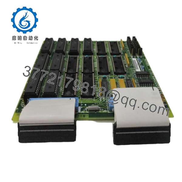
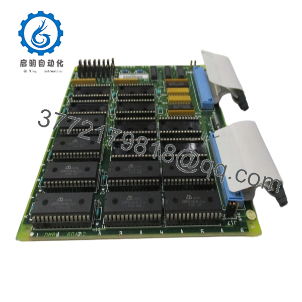
The GE DS3800DMPK1E1D is a voltage regulator board used in the Mark IV Speedtronic turbine control system. It manages voltage regulation functions to maintain stable electrical conditions for generator and control subsystems.
In field deployments, this board acts as a regulation layer between power electronics and control logic. It uses EPROM-based firmware and jumper-configurable settings, which means behavior is partially hardware-defined—this is typical for Mark IV-era designs where flexibility is limited compared to later Mark V/VI systems.
5. Installation & Configuration Guide
Stage 1: Pre-Installation Preparation (Estimated 10–15 minutes)
- ⚠️ Safety First: Shut down turbine/generator system, apply lockout/tagout, and wait at least 5 minutes for stored energy discharge.
- Tools Required: ESD wrist strap, flat-blade screwdriver (for EPROM handling), PH1 screwdriver, Fluke 115 multimeter, smartphone.
- Data Backup:
- Photograph EPROM placement and orientation (critical).
- Record jumper positions (pin 1–2 vs 2–3).
- Document cable routing and board slot.
Stage 2: Removing the Old Module (Estimated 5–10 minutes)
- Open cabinet and locate DS3800 board.
- Disconnect ribbon cables carefully.
- Remove mounting hardware or retention clips.
- Pull board straight out — avoid flexing.
- Carefully remove EPROM chips using a flat tool (alternate sides evenly).
- ⚠️ Note: Store EPROMs immediately in anti-static bags. Static can corrupt data.
Stage 3: Installing the New Module (Estimated 10–15 minutes)
- Wear ESD protection before handling.
- Verify exact model: DS3800DMPK1E1D.
- Install EPROMs into matching sockets (orientation notch matters).
- Replicate all jumper positions exactly.
- Insert board into rack and secure.
- Reconnect ribbon cables firmly.
- Self-Checklist:
- EPROMs correctly seated
- Jumpers match original
- Ribbon cables aligned and secured
Stage 4: Power-On & Testing (Estimated 10–15 minutes)
- Pre-Power Check: Verify no shorts on supply rails.
- Power-On Steps:
- Energize control cabinet.
- Monitor system diagnostics (if available).
- Verify voltage regulation behavior.
- Check for stable output under no-load conditions.
- Gradually return system to operation.
- ⚠️ Troubleshooting Note:
- No function → EPROM missing or incorrectly seated.
- Instability → jumper mismatch or corrupted EPROM.
6. Frequently Asked Questions (FAQ)
Q1: Can this board be hot-swapped?
No. Mark IV hardware is not designed for hot-swapping. You risk damaging the backplane and corrupting EPROM data.
Q2: Is this model obsolete?
Yes. Mark IV systems are long out of production. Most available units are surplus or refurbished, and stock is limited.
Q3: Do new boards come with EPROM chips installed?
Often, no. Many replacement boards ship without EPROMs, and you must transfer them from the original board.
Q4: What happens if I install EPROMs incorrectly?
The system won’t boot or will behave unpredictably. I’ve seen units sit idle for hours because one chip was offset by one pin.
Q5: Are all DS3800DMPK variants interchangeable?
Not reliably. Suffix differences (K1E1D, etc.) can reflect firmware or hardware changes. Always match the full part number.
Q6: What’s the most common failure mode?
EPROM degradation and connector wear. After years of thermal cycling, data retention issues and intermittent faults show up.
SOP Quality Transparency
1. Inbound Inspection & Traceability
- Verified against GE Mark IV part numbering.
- Serial and PCB revision inspected.
- Visual inspection: no socket damage, no PCB discoloration.
- EPROM sockets checked for pin integrity.
2. Live Functional Testing
- Tested on a GE Mark IV simulation rack.
- EPROM read/write verification performed.
- Voltage regulation behavior tested under simulated load.
- Continuous operation: 24-hour runtime test.
- Test report available (video/photos upon request).
3. Electrical Parameter Testing
- Insulation resistance >10 MΩ @ 500 V Megger.
- Ground continuity verified.
- Signal path continuity across ribbon connectors tested.
4. Firmware & Configuration Verification
- EPROM contents verified (checksum where applicable).
- Jumper configurations documented.
- Socket integrity checked.
5. Final QC & Packaging
- QC sign-off with traceable record.
- Anti-static ESD packaging (critical for EPROM protection).
- Foam-protected industrial carton.
- QC Passed label with date.

- DS3800DMPK1E1D
- DS3800DMPK1E1D
Technical Pitfall & Survival Guide
❗ 1. EPROM Handling Errors
This is where most failures happen.
Anecdote: A tech installed chips one pin offset—board powered but did nothing. Lost half a shift troubleshooting.
Avoidance: Double-check orientation notch and alignment.
❗ 2. Jumper Misconfiguration
There are 17 jumpers—each affects board behavior.
Avoidance: Photograph before removal. Replicate exactly.
❗ 3. Static Damage to EPROMs
EPROMs are extremely sensitive.
Real case: One static hit caused intermittent faults that took days to diagnose.
Avoidance: Use ESD bags and grounded handling.
❗ 4. Ribbon Cable Misalignment
34-pin connectors can be offset by one row.
Avoidance: Check alignment carefully before powering up.
❗ 5. Assuming It’s Plug-and-Play
It’s not. This is a configuration-dependent board.
Avoidance: Treat it like a firmware-bearing component, not a simple PCB swap.


