
 WhatsApp: +86 16626708626
 Email:
  Phone: +86 16626708626
Description
3. Key Technical Specifications
- Input Signal Type: Analog vibration signals (velocity/acceleration sensors)
- System Compatibility: GE Mark IV Speedtronic turbine control system
- Function Role: Vibration monitoring and protection interface
- Mounting Type: Rack-mounted PCB with card-edge connector
- Power Supply: Backplane powered (nominal 5 V DC / 24 V DC depending on rack design)
- Communication: Internal backplane bus (proprietary GE architecture)
- Operating Temperature: 0 to +60°C typical (cabinet-controlled environment)
- Humidity: 5–95% non-condensing
- Dimensions: Approx. 300 × 200 mm PCB format
- Weight: ~0.5 kg
- Compliance: Designed for legacy turbine control systems (pre-IEC 61131 standard PLC architecture)
4. Product Introduction
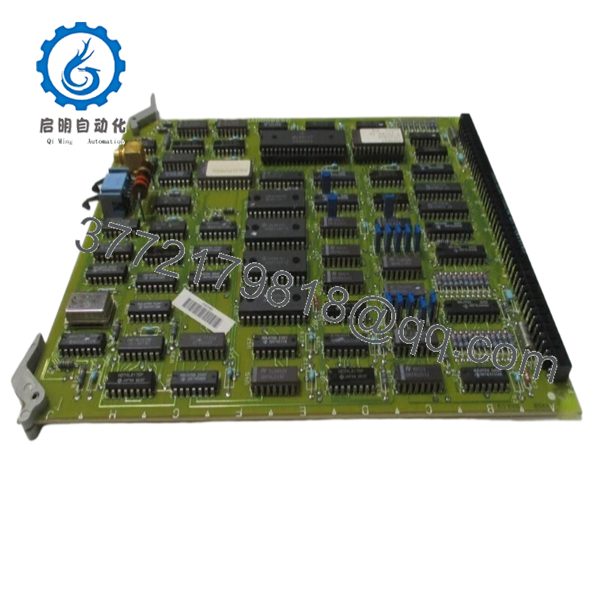
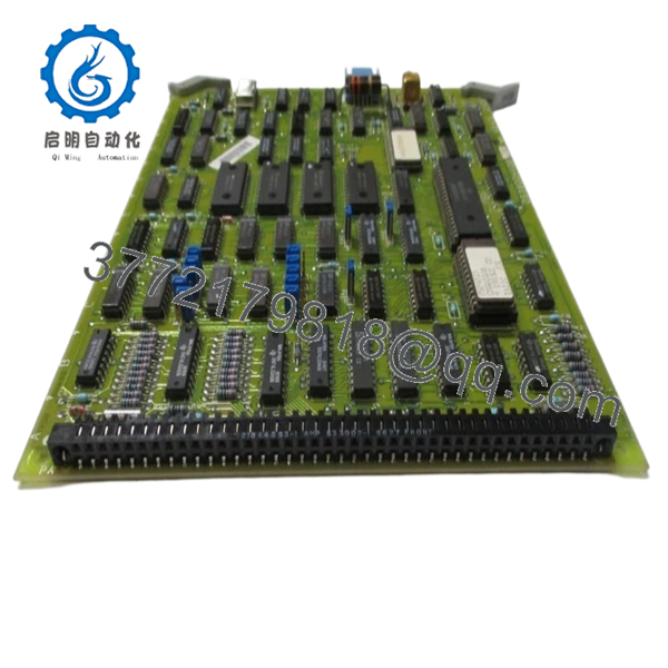
The GE DS3800HVDBIJIF is a vibration detection and processing board used in the Mark IV Speedtronic turbine control platform. It interfaces with field vibration sensors and feeds processed signals into the turbine protection logic.
In field deployments, this board plays a critical role in protecting rotating equipment by detecting abnormal vibration levels early. Compared to later Mark V/VI systems, Mark IV hardware like this requires exact part matching due to proprietary backplane signaling and limited firmware flexibility.
5. Installation & Configuration Guide
Stage 1: Pre-Installation Preparation (Estimated: 10 minutes)
- ⚠️ Safety First:
Notify operations, bring turbine/system to a safe shutdown state.
Lock out/tag out all power sources. Wait at least 5 minutes for capacitors to discharge. - Tools Required:
ESD wrist strap, PH1 screwdriver, multimeter, labeling tags, smartphone - Data Backup:
- Document current system configuration (Mark IV has limited software backup; rely on physical records)
- Photograph board slot position and wiring interfaces
- Record any adjacent board part numbers for reference
Stage 2: Removing the Old Module (Estimated: 5–10 minutes)
- Open the control cabinet and locate the DS3800HVDBIJIF board.
- Label all connected wiring or interface cables.
- Carefully disconnect connectors — do not force aged terminals.
- Release retaining clips or screws.
- Pull the board straight out to avoid bending backplane pins.
- Inspect rack connector for dust, oxidation, or bent pins.
- ⚠️ Note: Keep the old board until the replacement is fully verified operational.
Stage 3: Installing the New Module (Estimated: 10 minutes)
- Wear ESD protection before handling the PCB.
- Verify exact model match: DS3800HVDBIJIF (suffix must match).
- Inspect for shipping damage or loose components.
- Insert the board into the same slot, ensuring proper alignment.
- Apply even pressure until fully seated in the backplane.
- Secure retaining clips/screws.
- Reconnect all wiring exactly as labeled.
- Self-Checklist:
- Correct slot position
- Connectors fully seated
- No bent pins
- Board firmly secured
Stage 4: Power-On & Testing (Estimated: 10–15 minutes)
- Pre-Power Check:
Use a multimeter to confirm no short circuits on supply rails. - Power-On Steps:
- Power up the control rack only.
- Observe system diagnostics (Mark IV uses panel indicators rather than modern LEDs).
- Verify no fault alarms related to vibration channels.
- Check vibration readings against baseline values.
- Perform a dry-run simulation if possible (inject known signal).
- ⚠️ Troubleshooting Note:
If vibration channels show zero or erratic values, check:- Sensor wiring integrity
- Backplane connector seating
- Compatibility with adjacent processing boards

- DS3800HVDBIJIF
- DS3800HVDBIJIF
6. Frequently Asked Questions (FAQ)
Q1: Can I hot-swap the DS3800HVDBIJIF under power?
No. The Mark IV system does not support hot-swapping. Removing or inserting a board under power can damage the backplane or cause a system trip. Always shut down first.
Q2: Is this model obsolete, and is it truly new?
Yes, it is obsolete. GE no longer manufactures Mark IV boards. “New Original / New Surplus” means unused inventory stored under controlled conditions. Always confirm storage history if long-term reliability is critical.
Q3: What is the direct replacement if this unit is unavailable?
There is no true drop-in replacement outside the Mark IV ecosystem. Migration typically involves upgrading to Mark V or Mark VIe systems, which requires significant engineering changes.
Q4: Will I lose system logic if I replace this board?
No. This board does not store control logic. Logic resides in the main control processors. However, removing it may trigger alarms or trips if the system is powered.
Q5: Why are surplus units priced lower than OEM historical pricing?
Because they come from excess inventory or decommissioned projects. You’re not paying for current OEM support or production—just the hardware itself. That said, availability is finite.
Q6: How do I verify this board is functioning correctly after installation?
Check for stable vibration readings, no fault alarms, and consistency with historical baseline data. If possible, inject a calibrated signal to confirm measurement accuracy.
SOP Quality Transparency
1. Inbound Inspection & Traceability
- Verified against original GE packing references where available
- Serial number and PCB revision visually confirmed
- Inspected for corrosion, solder rework, connector wear, and UV discoloration
- Accessory check (where applicable)
2. Live Functional Testing
- Tested in a simulated Mark IV rack environment (compatible backplane setup)
- Power-on verification and signal path validation
- Analog signal injection to confirm vibration processing
- Continuous operation test >24 hours with thermal observation
- Test report available upon request
3. Electrical Parameter Testing
- Insulation resistance test using 500 V Megger (>10 MΩ)
- Ground continuity verified
- Voltage rail stability confirmed
4. Firmware & Configuration Verification
- Mark IV boards are hardware-driven; no firmware mismatch issues typical
- Jumper/solder configuration visually documented
5. Final QC & Packaging
- QC sign-off with date labeling
- Anti-static ESD packaging
- Shock-protected industrial-grade boxing
Technical Pitfall & Survival Guide
❗ 1. Slot Misplacement in Rack
- Issue: Installing the board in the wrong slot causes system faults or no signal processing.
- Avoidance: Always match the exact slot position from the original setup.
- Field note: I’ve seen engineers swap adjacent boards and spend hours chasing phantom faults.
❗ 2. Connector Wear on Legacy Systems
- Issue: Old backplane connectors lose tension, causing intermittent faults.
- Avoidance: Inspect carefully and reseat firmly.
- Reality: Mark IV systems are decades old—mechanical wear is a real factor.
❗ 3. Signal Calibration Drift
- Issue: Replacement board may show slight deviation in readings.
- Avoidance: Compare with historical baseline and recalibrate if required.
- Anecdote: A turbine tripped because a 5% deviation wasn’t checked after replacement.
❗ 4. Power Supply Margins
- Issue: Aging power supplies may not handle stable voltage under load.
- Avoidance: Measure 5 V and 24 V rails under operation. Leave a 20% margin.
❗ 5. ESD Damage During Handling
- Issue: Static discharge destroys sensitive analog components.
- Avoidance: Always use an ESD strap and grounded workspace.
- Real case: Board powered up fine, failed 2 hours later—classic latent ESD damage.


