
 WhatsApp: +86 16626708626
 Email:
  Phone: +86 16626708626
Description
3. Key Technical Specifications
| Parameter | Value |
|---|---|
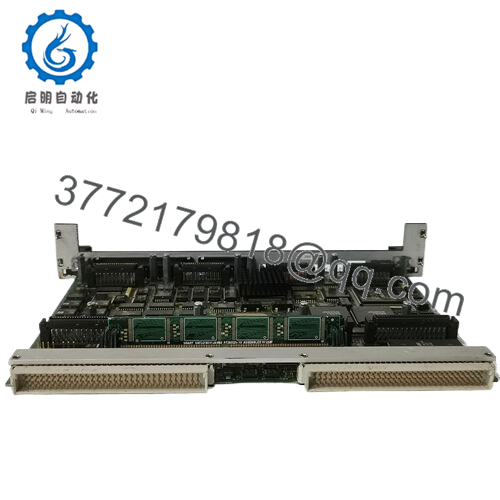
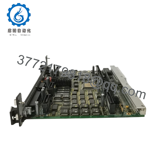
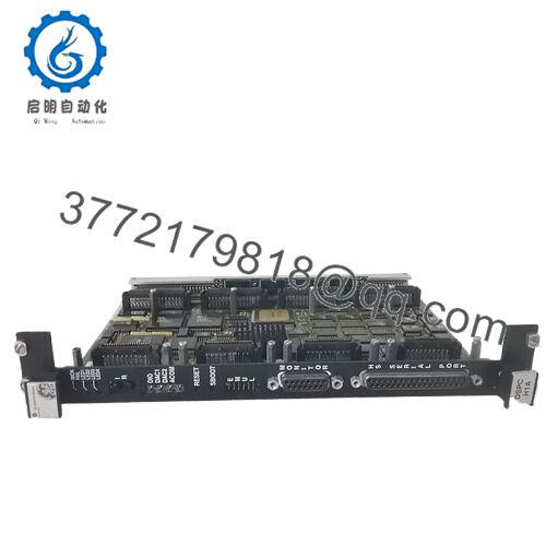
| Model | DS3800HXPD1C1E |
| Brand | GE (General Electric) |
| Series | Mark IV Speedtronic |
| Board Type | High Power Servo Control Board (Servo Valve Driver) |
| Power Supply | +5V DC, ±15V DC from backplane |
| Current Draw | +5V: 1.2A, +15V: 1.0A, -15V: 1.0A |
| Command Input | 4-20 mA or ±10V (jumper selectable) |
| Position Feedback | LVDT (Linear Variable Differential Transformer) or DC LVDT |
| LVDT Excitation | 3 kHz, 5V RMS (internal oscillator, 10V RMS optional) |
| Servo Output | ±100 mA continuous, ±200 mA peak into 20-40 ohm coil |
| Output Type | Push-pull linear amplifier (Class AB) |
| Bandwidth | DC to 150 Hz (-3 dB) |
| Linearity | ±0.1% of full scale |
| Dither Frequency | 100 Hz to 500 Hz (adjustable, 250 Hz default) |
| Dither Amplitude | 0 to 30% of full scale (adjustable) |
| Null Adjustment | ±25% of span (potentiometer, 10-turn) |
| Gain Adjustment | 0.2 to 20 (potentiometer, 10-turn) |
| Status LEDs | 5 x LEDs (Power OK, LVDT OK, Command Active, Positive Output, Negative Output) |
| Test Points | 8 x TP (Command, Feedback, Error, Output+, Output-, LVDT P1, LVDT S1, LVDT S2) |
| Trim Pots | 5 x 10-turn (Null, Gain, Dither Frequency, Dither Amplitude, LVDT Balance) |
| DIP Switches | 12-position (configuration for servo type, LVDT type, fault logic) |
| Operating Temp | 0 to +50°C (32 to 122°F) |
| Storage Temp | -40 to +85°C (-40 to 185°F) |
| Dimensions | 9.5 x 6.5 x 1.2 inches (approx) |
| Connectors | 1 x 96-pin backplane, 1 x 37-pin D-sub (field I/O) |
| GE Part Family | DS3800 (Mark IV) |
4. Product Introduction
The GE DS3800HXPD1C1E is the HXPD high power servo control board for the Mark IV Speedtronic turbine control system. This board drives large electro-hydraulic servo valves (EHSV) that position main steam stop valves, intercept valves, and reheat valves on high-megawatt gas and steam turbines. You’ll find it in applications requiring higher coil drive current than the standard DSHA board can provide.
The HXPD board delivers ±100 mA continuous (200 mA peak) into servo valve coils with 20-40 ohm resistance. It takes a 4-20 mA or ±10V command from the main processor, reads LVDT position feedback, and closes the loop entirely in analog hardware. Key features: 10-turn trim pots for precision adjustment, LVDT balance adjustment for DC LVDTs, and a wider bandwidth (150 Hz) for fast-acting valves. If your turbine has large-bore valves or high-flow hydraulic actuators, this is the board you need. When the HXPD fails, the valve goes to its fail-safe position, and the turbine trips.
5. Installation & Configuration Guide
Estimated time for replacement by a qualified technician: 60 minutes
Stage 1: Pre-Installation Preparation (15 minutes)
⚠️ Safety First: Notify operations of turbine shutdown. Verify steam supply locked out. Depressurize the hydraulic power unit (HPU). Wait 5 minutes for hydraulic pressure to bleed down. Lock out/tag out the HPU motor starter.
Tools Required:
- ESD wrist strap grounded to earth (not just panel ground)
- Small flathead screwdriver (2.5mm) for trim pots
- Phillips #1 screwdriver for terminal blocks
- Precision 10-turn pot adjustment tool (or small flathead)
- Multimeter with true RMS capability (Fluke 87V or equivalent)
- LVDT simulator (variable transformer with center tap)
- 4-20 mA calibrator
- Smartphone for photos
- Notebook for recording pot positions (10-turn pots require counting turns)
Data Backup:
- Photograph the 12-position DIP switch bank. Record every switch position (1-12).
- Record the exact number of turns from full CCW for each of the 5 trim pots:
- Null: ___ turns from CCW stop
- Gain: ___ turns from CCW stop
- Dither Frequency: ___ turns from CCW stop
- Dither Amplitude: ___ turns from CCW stop
- LVDT Balance: ___ turns from CCW stop
- Photograph all jumper positions (command type, LVDT type, output configuration).
- Document the valve coil resistance (measure at the 37-pin connector). Should be 20-40 ohms.

- DS3800HXPD1C1E
Stage 2: Removing the Old Module (10 minutes)
Step 1: Remove the 37-pin D-sub connector (field wiring). Loosen both jackscrews completely. Do not pull on the cable.
Step 2: Label the connector if not already marked. Use permanent labels, not tape.
Step 3: Release the board ejectors (top and bottom). Pull the board straight out. No rocking — backplane pins bend easily.
Step 4: Inspect the backplane connector for bent pins, corrosion, or debris. Use a flashlight. Bent pins require backplane replacement — do not force a new board in.
Step 5: Place the old board on an ESD mat. Keep it for reference until the new board is fully tuned.
Stage 3: Installing the New Module (20 minutes)
Step 1 (ESD): Ground your wrist strap. Unpack the new DS3800HXPD1C1E on an ESD mat.
Step 2 (Verify Model): Confirm the new board label reads DS3800HXPD1C1E. The “1C1E” suffix matters for LVDT excitation voltage (5V RMS vs 10V RMS). Do not substitute earlier revisions without checking LVDT compatibility.
Step 3 (Clone DIP Switches — Critical):
- Set all 12 DIP switches exactly as photographed.
- Pay special attention to switch 5 (LVDT type: AC or DC) and switch 6 (excitation voltage: 5V or 10V RMS). Wrong settings will damage a DC LVDT or give incorrect feedback.
Step 4 (Set Trim Pots to Recorded Positions):
- Turn each pot fully counterclockwise (CCW) until it clicks (end stop).
- Advance clockwise by the recorded number of turns.
- For example: Gain = 5.5 turns from CCW. Turn fully CCW, then turn clockwise 5.5 turns.
Step 5 (Verify Jumpers): Check all jumpers match the old board. Critical jumper: J1 (command input type — 4-20 mA or ±10V).
Step 6: Insert the board into the original slot. Push evenly until both ejectors latch fully. You should hear a distinct click.
Step 7: Reconnect the 37-pin D-sub. Tighten jackscrews to 5 in-lbs (finger-tight plus 1/4 turn with a screwdriver). Overtightening strips the threads.
Self-Checklist:
- DIP switches 1-12 match old board exactly
- All 5 trim pots at recorded turn counts
- Jumpers verified (J1, J2, J3)
- Board fully seated (ejectors horizontal)
- 37-pin connector secured
Stage 4: Power-On & Testing (15 minutes)
Pre-Power Check:
Measure resistance between servo output pins (A and B) and ground. Should be >10k ohms. Measure coil resistance between A and B: should match your valve spec (20-40 ohms). Below 15 ohms indicates a shorted coil — do not power up until resolved.
Power-On Steps:
- Power up the Mark IV rack (24V and ±15V supplies). Do not apply hydraulic pressure yet.
- Observe the HXPD LEDs:
- Power OK (green): Must be on.
- LVDT OK (green): On if LVDT connected and balanced. If off, check wiring.
- Fault (red): Must be off. On indicates null error or LVDT failure.
- Connect the maintenance terminal. Command 0% valve position (12mA or 0V).
- Measure servo output current between A and B pins. Should be 0 mA ±3 mA.
- Null adjustment: If output current is not zero, adjust the Null pot (10-turn) until output reads 0 mA. One full turn changes output by approximately ±10 mA.
- Apply hydraulic pressure (coordinate with operations). Monitor valve position feedback.
- Ramp command from 0% to 50% to 100% in 10% steps. Feedback should track within ±1% with no overshoot.
- Gain adjustment: If response is sluggish, increase Gain clockwise. If valve oscillates at steady state, reduce Gain counterclockwise.
- Dither adjustment: If valve sticks at low commands (below 10%), increase Dither Amplitude clockwise. If valve buzzes audibly, reduce Dither Amplitude or adjust Dither Frequency.
⚠️ Troubleshooting:
| Symptom | Likely Cause | Action |
|---|---|---|
| Fault LED on, LVDT OK off | LVDT wiring reversed, open, or wrong type | Check LVDT wiring. Measure primary resistance (50-200 ohms). Swap secondary wires A/B. |
| Valve oscillates at steady command (hunting) | Gain too high or LVDT balance off | Reduce Gain by 2 turns. Adjust LVDT Balance pot until feedback stabilizes. |
| Valve moves to full stroke at 0% command | Null offset or command signal wrong | Measure command input (should be 12mA at 0%). Adjust Null pot to center valve. |
| No response to command, output stuck at 0 mA | Command signal missing or output driver failed | Measure command at input terminals. If present, output driver likely failed — replace board. |
| Output current stuck at ±100 mA (valve hard over) | Shorted output transistor or coil short to ground | Remove power. Measure coil resistance. If coil is good (20-40 ohms), output stage failed — replace board. |
| LVDT feedback jumps or noisy | Shield ground loop or cable too long | Ground shield at board end only. Keep LVDT cable under 30 meters. Replace board if noise persists. |
| Valve moves but overshoots significantly | Gain too high or system response too fast | Reduce Gain. Increase Dither Amplitude slightly (reduces stiction-induced overshoot). |
6. Frequently Asked Questions (FAQ)
Q: Is the DS3800HXPD1C1E a direct replacement for HXPD1C1D or HXPD1C1C?
A: Yes, with verification of LVDT excitation voltage. The suffix “1E” indicates 5V RMS LVDT excitation. “1D” and “1C” may have 10V RMS excitation. Check your LVDT datasheet. Applying 10V to a 5V-rated LVDT will overheat the primary winding. Applying 5V to a 10V LVDT will give half the output signal, causing reduced position accuracy. Set DIP switch 6 to match your LVDT’s required excitation. If uncertain, measure the excitation voltage on your old board with a true RMS meter.
Q: Can I use the HXPD board in place of a standard DSHA board?
A: Yes, but you must recalibrate the valve response. The HXPD has higher gain range and higher output current. If your valve requires only ±50 mA, the HXPD will work, but you’ll have less resolution (the output is ±100 mA, so half your command range uses the full output). Set the Gain pot lower (start at 2 turns from CCW) to compensate. However, do not use a DSHA (50 mA) in place of an HXPD (100 mA) — the DSHA will not drive a 20-40 ohm coil to full stroke.
Q: Why does the HXPD have 10-turn pots instead of single-turn like the DSHA?
A: The HXPD is designed for precision tuning on large valves. A 10-turn pot gives 10x finer adjustment. One full turn changes gain by a factor of 2 (e.g., from 2 to 4). For a single-turn pot, a 1-degree rotation changes gain by 10x — too coarse. Record the exact number of turns, not just the clock position. We recommend using a 10-turn counting dial or marking the pot body with a reference line.
Q: Can I hot-swap the HXPD board while the turbine is running?
A: No. The HXPD drives the servo valve directly. Removing the board removes coil current. The valve will go to its fail-safe position (spring-loaded closed for stop valves, spring-loaded open for some intercept valves). The turbine will trip. Procedure: Shut down the turbine. Lock out steam and hydraulic pressure. Remove rack power. Then swap. Never remove an HXPD with hydraulic pressure applied — the valve may slam to the stop, damaging the actuator or valve stem.
Q: How do I adjust LVDT Balance on the HXPD?
A: The LVDT Balance pot compensates for mechanical offset in the LVDT core. Procedure:
- Command 0% valve position (12mA).
- Physically center the valve actuator (use the manual override or null hydraulic bypass).
- Adjust LVDT Balance pot until the feedback reading in the maintenance terminal reads 0%.
- Ramp to 50% and 100%. Feedback should be linear (±1%).
If you cannot achieve 0% feedback at mechanical center, the LVDT mounting bracket is misaligned — adjust mechanically first, then use the Balance pot.
Q: My HXPD board works but runs hot (above 65°C). Is this normal?
A: The HXPD dissipates up to 6W in the output transistors at full ±100 mA output. Normal operating temperature is 50-65°C (122-149°F) at 25°C ambient. Above 70°C, investigate:
- Valve coil resistance too low: Measure coil resistance. Below 15 ohms draws >100 mA at ±12V output, exceeding the board’s rating.
- Output stage oscillating: Connect an oscilloscope to the output test point. Look for high-frequency (>1 kHz) oscillation. Replace board if present.
- Poor airflow: Ensure the rack has unobstructed airflow. Add a panel fan if multiple HXPD boards are stacked.
Q: What’s the difference between HXPD and other Mark IV high power servo boards?
A: Quick reference:
- HXPD (DS3800HXPD): High power servo driver, ±100 mA, 10-turn pots, LVDT balance adjustment.
- HXPE (DS3800HXPE): Extended range, ±150 mA output, for very large valves (e.g., main stop valves on 200+ MW turbines).
- DSHA (DS3800DSHA): Standard power, ±50 mA, single-turn pots.
- HSVC (DS3800HSVC): High speed servo for fast-acting dump valves (different pinout, not interchangeable).
The HXPD is the standard high power board for most large GE turbines (Frame 7 and 9 gas turbines, large steam turbines). Check your valve coil rating before ordering.
Q: How do I bench test the HXPD without a turbine valve?
A: You need a ±15V and +5V power supply (3A minimum) and a 25-40 ohm dummy load resistor (25W minimum). Procedure:
- Apply power to the board.
- Connect a 33 ohm, 25W resistor between output A and B.
- Connect an LVDT simulator (three variable transformers ganged) or a known-good LVDT.
- Apply 12mA command (0% position).
- Adjust Null pot until output current reads 0 mA ±1 mA.
- Ramp command to 20mA (+100%). Output current should reach +100 mA ±5 mA.
- Measure voltage across the resistor. For 33 ohms and 100 mA, voltage should be 3.3V ±0.2V.
- Ramp command to 4mA (-100%). Output current should reach -100 mA ±5 mA.
Without an LVDT simulator, the board will fault (no feedback). We can provide a test report from our Mark IV test stand with a real servo valve.
Q: What’s your testing process for this board?
A: We test every DS3800HXPD1C1E on a live Mark IV test stand with a genuine high-current servo valve (Moog D633 series or equivalent, 33 ohm coil) and LVDT. Test sequence:
- Visual inspection (burnt output transistors, cracked pots, corrosion)
- Power-on test (current draw: +5V: 1.2A, ±15V: 1.0A each)
- LVDT excitation test: 5V RMS at 3 kHz ±0.1V (measure with true RMS meter)
- Command input test: 4-20 mA and ±10V, verify scaling within ±0.2%
- Servo output test: ±100 mA into 33 ohm load, linearity ±0.2%, 0.1% steps
- Null adjustment verification: 0 mA ±1 mA at 12mA command
- Gain verification: output change per mA command (should be 12.5 mA/mA typical)
- Dither test: 100-500 Hz, amplitude 0-30%, verify with oscilloscope
- LVDT balance test: center feedback at mechanical null
- 48-hour burn-in with 50% command (50 mA output) and thermal monitoring (max temp <70°C)
Test report with as-found null and gain values (turns from CCW), recommended settings for your valve type, and thermal images available upon request.
Q: My turbine has been running for 25 years on the original HXPD. Should I replace it proactively?
A: Yes. The HXPD uses high-power output transistors that degrade with thermal cycling. After 25 years, the solder joints under the TO-3 transistors can crack, causing intermittent output. Symptoms: valve sputters, turbine load fluctuates, intermittent “Servo Fault” alarms that clear on reset. Proactive replacement costs less than a turbine trip during peak demand. Keep a spare on site. Rotate spares annually — install the spare, run for one week, then test the removed board. Keep the better one as the new spare.
Q: What’s the warranty on this obsolete board?
A: 1-year replacement warranty. Covers failure under normal operating conditions (0-50°C, correct backplane voltages, valve coil resistance 20-40 ohms). Does NOT cover damage from shorted valve coils (below 15 ohms), incorrect wiring (applying 120V AC to servo outputs), hydraulic oil contamination, ESD, or physical damage to 10-turn pots. We cross-ship replacements within 24 hours for confirmed defects. We also offer a 30-day tuning guarantee — if the board works but you cannot achieve stable valve control within the adjustment range, return it for full credit.


