
 WhatsApp: +86 16626708626
 Email:
  Phone: +86 16626708626
Description
3. Key Technical Specifications
- Function: Analog-to-digital conversion for turbine control signals
- System Compatibility: GE Mark IV Speedtronic control platform
- Input Type: Analog signals (typical: 4–20 mA, ±10 V depending on configuration)
- Output Type: Digital signals to Mark IV processor bus
- Architecture: Backplane-integrated processing (proprietary GE bus)
- Power Supply: Backplane powered (5 V DC / 24 V DC typical Mark IV rails)
- Resolution: Typical industrial A/D conversion (exact bit depth varies by revision; verify before install)
- Mounting: 6U rack-mounted PCB with card-edge connector
- Operating Temperature: −20 to +70°C (cabinet dependent)
- Humidity: 5–95% non-condensing
- Dimensions: Standard Mark IV Eurocard format (~160 × 233 mm)
- Weight: ~0.3–0.5 kg
4. Product Introduction
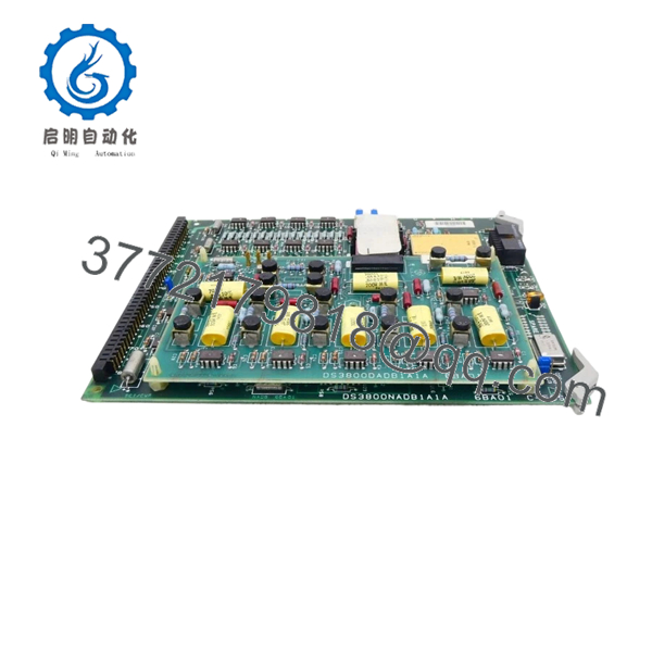
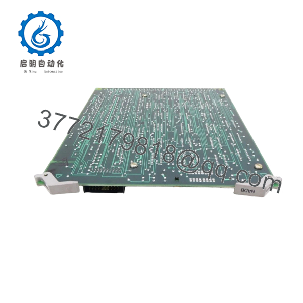
The GE DS3800NADB1A1A is an analog-to-digital converter board used within the Mark IV Speedtronic turbine control system. It converts field analog signals—such as pressure, temperature, and vibration—into digital values for processing by the control CPU.
In real plant deployments, this board sits in the signal chain between field instrumentation and control logic. Compared to later Mark V/VI platforms, the Mark IV architecture relies heavily on discrete conversion boards like this, meaning replacements must match exactly—there is no abstraction layer or flexible firmware handling.
5. Installation & Configuration Guide
Stage 1: Pre-Installation Preparation (Estimated: 10 minutes)
- ⚠️ Safety First:
Coordinate shutdown with operations. Lock out/tag out all power sources. Wait minimum 5 minutes for discharge. - Tools Required:
ESD strap, PH1 screwdriver, multimeter, labeling tags, smartphone - Data Backup:
- Record all analog channel assignments
- Photograph terminal wiring and board slot position
- Document signal scaling (4–20 mA, ±10 V, etc.)
Stage 2: Removing the Old Module (Estimated: 5–10 minutes)
- Open cabinet and locate DS3800NADB1A1A.
- Label all signal wiring carefully (channel mix-ups are common).
- Disconnect wiring—avoid stressing aged terminals.
- Release locking clips or screws.
- Pull the board straight out to protect backplane connectors.
- Inspect for dust or oxidation.
- ⚠️ Note: Keep the original board until full system validation.
Stage 3: Installing the New Module (Estimated: 10 minutes)
- Wear ESD protection.
- Verify exact model and suffix match (DS3800NADB1A1A).
- Inspect jumper or configuration settings.
- Insert board into correct rack slot—align carefully.
- Seat fully until connector engagement is firm.
- Reconnect wiring exactly as labeled.
- Self-Checklist:
- Channel wiring correct
- Board fully seated
- No bent pins
- Configuration matches original
Stage 4: Power-On & Testing (Estimated: 10–15 minutes)
- Pre-Power Check:
Confirm no shorts on analog input circuits. - Power-On Steps:
- Power up rack only.
- Check system status indicators.
- Verify analog input values in HMI/diagnostics.
- Compare readings to known baseline values.
- Inject test signals if available (loop calibrator recommended).
- ⚠️ Troubleshooting Note:
- Flatline readings → wiring or scaling mismatch
- No data → backplane seating or channel config issue
- Erratic values → grounding or shielding problem

- DS3800NADB1A1A
6. Frequently Asked Questions (FAQ)
Q1: Can I hot-swap this board?
No. Mark IV systems are not designed for live insertion. You risk damaging the backplane or corrupting signal processing. Always power down.
Q2: Is DS3800NADB1A1A obsolete?
Yes. Mark IV hardware has been out of production for decades. Availability depends on surplus inventory.
Q3: Is DS3800NADB1B1B a compatible alternative?
Sometimes, but not guaranteed. It’s a similar A/D converter variant, but revision differences may affect signal scaling or connector mapping. Always verify against GE documentation.
Q4: Will replacing this board affect control logic?
No, logic resides in the main processor. However, incorrect signal conversion will impact control decisions immediately.
Q5: Why is signal accuracy different after replacement?
Different revisions may have slight calibration offsets. You may need to recalibrate loops after installation.
Q6: Why are surplus units cheaper than OEM historical pricing?
You’re buying legacy inventory without OEM support. No factory warranty, limited stock, and varying storage conditions.
SOP Quality Transparency
1. Inbound Inspection & Traceability
- Verified against OEM references and labeling
- Serial and revision markings checked
- Visual inspection: no corrosion, no solder rework, no connector damage
- Accessories verified where applicable
2. Live Functional Testing
- Tested on a Mark IV-compatible rack simulator
- Analog signal injection using calibrated source (Fluke 724)
- Verified A/D conversion accuracy across full scale
- Continuous run test >24 hours with thermal monitoring
- Test report available upon request
3. Electrical Parameter Testing
- Insulation resistance test: 500 V Megger (>10 MΩ)
- Ground continuity verified
- Power rail stability confirmed
4. Firmware & Configuration Verification
- Hardware-based configuration checked (jumpers if present)
- No firmware dependency typical for this board class
5. Final QC & Packaging
- QC sign-off with traceable record
- Anti-static ESD packaging
- Shock-resistant industrial boxing
Technical Pitfall & Survival Guide
❗ 1. Signal Scaling Mismatch
- Issue: Incorrect interpretation of 4–20 mA vs ±10 V inputs
- Avoidance: Document original scaling before removal
- Real case: I’ve seen a pressure loop read 0% because scaling wasn’t matched
❗ 2. Channel Wiring Errors
- Issue: Swapped inputs cause incorrect control actions
- Avoidance: Label every wire before removal
- Reality: This is one of the most common commissioning mistakes
❗ 3. Grounding and Shielding Problems
- Issue: Noise introduces unstable readings
- Avoidance: Maintain original shielding and grounding scheme
- Field note: Turbine environments are electrically noisy—don’t improvise grounding
❗ 4. Power Rail Degradation
- Issue: Old power supplies introduce ripple affecting A/D accuracy
- Avoidance: Measure 5 V rail under load
❗ 5. ESD Damage During Handling
- Issue: Latent failure after installation
- Avoidance: Use proper grounding
- I’ve personally seen boards fail hours later due to static damage


