
 WhatsApp: +86 16626708626
 Email:
  Phone: +86 16626708626
Description
3. Key Technical Specifications
| Parameter | Value |
|---|---|
| Input Voltage | 100–240V AC (47–63 Hz) or 125V DC |
| Input Current | 2.0A max at 120V AC |
| Output Voltages | +5V DC (15A), +15V DC (3A), -15V DC (3A) |
| Output Power | 100W continuous max |
| Ripple & Noise | <30 mV peak-to-peak on +5V, <50 mV on ±15V |
| Efficiency | 70% typical |
| Hold-up Time | 20 ms at full load |
| Isolation | Input to output: 1500V AC |
| Operating Temp | 0 to +50°C (32 to 122°F) |
| Storage Temp | -40 to +85°C (-40 to 185°F) |
| Humidity | 10% to 90% non-condensing |
| Dimensions | 10.5 x 7.0 x 2.0 inches (approx) |
| Connectors | 1 x 32-pin edge connector (backplane), 1 x terminal block |
| Status LEDs | +5V OK, +15V OK, -15V OK, AC Input OK |
| GE Part Family | DS3800 (Mark IV) |
4. Product Introduction
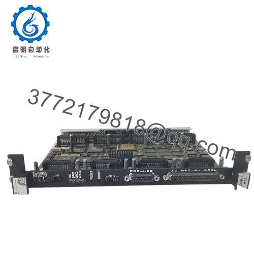
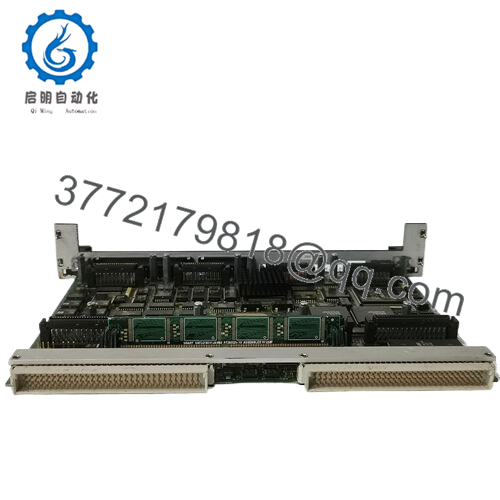
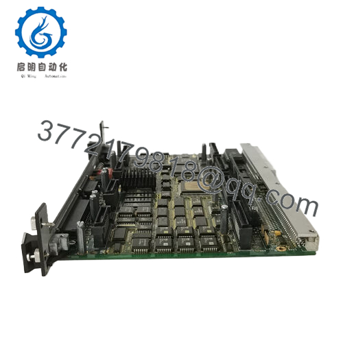
The GE DS3800NPSR1A1A is the NPSR power supply board for the Mark IV Speedtronic turbine control system. This board accepts either 120/240V AC or 125V DC field power and generates the regulated +5V, +15V, and -15V DC required by Mark IV processor, I/O, and communication boards. You’ll find this in legacy gas and steam turbine applications, including Frame 3, 5, 6, and 7 units from the 1980s and 1990s.
The NPSR design uses linear and switching hybrid regulation. The +5V rail handles most of the load (up to 15A) for TTL logic. The ±15V rails power analog circuits and op-amps. Unlike later Mark V designs, the Mark IV backplane has no redundant power input. When this board fails, the entire rack goes dark. Keep a spare on hand.
5. Troubleshooting Quick Reference
| Symptom | Possible Cause | Relevance to this Part | Quick Check Method | Recommendation |
|---|---|---|---|---|
| No LEDs lit on NPSR | Input power missing or blown internal fuse | ✅ High | Measure input at terminal block: 120V AC L-N or 125V DC +/-. | Check upstream breaker and wiring. Replace NPSR if input present but no LEDs. |
| +5V LED off, other LEDs on | +5V regulator failed or shorted load | ✅ High | Disconnect backplane (remove board). Apply power and measure +5V output pins. If present, load on backplane is shorted. | If no output with no load, board failed. If output appears, check downstream boards for shorts. |
| Turbine trips randomly, watchdog faults | Ripple too high on +5V rail | ✅ High | Measure +5V with oscilloscope at backplane pins. Ripple >100mV indicates capacitor aging. | Replace NPSR preemptively. High ripple corrupts backplane communication. |
| +15V measures +12V or lower | Regulator drift or bad capacitor | ✅ High | Measure under load (board installed in rack). Compare to no-load test. | Replace board. Do not operate analog inputs with low +15V — readings will be non-linear. |
| Board runs hot, smells | Overload or shorted output filter cap | ✅ High | Measure resistance from +5V to ground (power off, board removed). Below 5 ohms indicates short. | Replace immediately. Fire risk in old panels with dust buildup. |
| Intermittent operation, works after reboot | Thermal intermittent on solder joint | ✅ High | Apply heat gun (gentle, 60°C) to board while monitoring outputs. Watch for dropout. | Not field repairable. Replace board. |
| All voltages correct but rack won’t boot | Power Good signal missing or wrong timing | ✅ High | Check edge connector pin A30 (Power Good). Should be TTL high (5V) 100ms after outputs stable. | Signal failure requires replacement. No workaround. |
Tech Note: The NPSR board uses electrolytic capacitors that dry out after 20+ years. If your Mark IV is still running on original power supplies, you’re on borrowed time. We recommend proactive replacement during scheduled outages.
- DS3800NPSR1A1A
6. Frequently Asked Questions (FAQ)
Q: Is the DS3800NPSR1A1A compatible with all Mark IV racks?
A: Yes, with one caveat. The NPSR board works in any Mark IV rack (P1, P2, P3, or P5 backplane variants). However, very early racks (pre-1987) used a different keying on the edge connector. Check your backplane slot. If your existing board has a notch in a different position, you’ll need to modify the keying or use an adapter. Send us a photo of your backplane slot and we’ll verify.
Q: Can I use an AC input and DC input at the same time?
A: No. The board has a single input section. Wire either AC (L-N-G) OR DC (+/-). Never apply both simultaneously. The isolation diodes will fail, and you’ll let the smoke out. We’ve seen it happen.
Q: Why is this board so expensive for its age?
A: Supply and demand. GE stopped making Mark IV parts in 2005. Thousands of turbines still run on Mark IV systems. New surplus boards like this one are the only genuine OEM option. Refurbished boards exist, but we’ve seen high failure rates from shops that just recap and resell. This is new old stock — never installed.
Q: What’s your return policy if this board doesn’t work in my rack?
A: 30-day return for DOA (dead on arrival). Test the board on your bench before installing in a live turbine. Apply AC power and verify all three output voltages and LEDs. If it fails within 30 days, we cross-ship a replacement. After 30 days, the 1-year warranty covers defects but not compatibility issues — verify fitment before ordering.
Q: Can I repair my NPSR board by replacing capacitors?
A: You can try. But we don’t recommend it for turbine control. The NPSR uses multi-layer PCBs with plated through-holes. Desoldering 30-year-old caps often lifts pads. Also, the linear regulator pass transistors and optocouplers drift with age. We’ve seen “recapped” boards fail within 100 hours. If your plant can’t tolerate unplanned downtime, buy a spare instead of repairing.
Q: How do I bench test the NPSR without a Mark IV rack?
A: Simple. Connect 120V AC to the terminal block (L to black, N to white, G to green). Use a multimeter to measure between these edge connector pins (component side facing you, pin 1 on left):
- +5V: pins A1-A8 (any) to A9-A16 (GND)
- +15V: pins A17-A20 to A21-A24 (GND)
- -15V: pins A25-A28 to A21-A24 (GND)
All voltages should be within ±5% with no load. The board will run warm — normal.
Q: My existing NPSR has a different suffix (DS3800NPSR1B1A). Will this work?
A: The “1A1A” vs “1B1A” indicates a minor revision change. The 1B version added MOVs (metal oxide varistors) for better surge protection. Electrically identical otherwise. The 1A1A will work as a direct replacement. No firmware or configuration differences exist — the NPSR has no programmable components.


