

 WhatsApp: +86 16626708626
 Email:
  Phone: +86 16626708626
Description
3. Key Technical Specifications
- Function: Excitation control and signal processing within turbine system
- System Compatibility: GE Mark IV Speedtronic platform
- Architecture: Backplane-integrated PCB (proprietary GE bus)
- Processing Role: Interfaces excitation signals with control logic
- Power Supply: Backplane powered (5 V DC / 24 V DC typical Mark IV rails)
- Mounting: Rack-mounted Eurocard PCB with extractor levers
- Indicators: Onboard LED indicators (status/diagnostics typical for DS3800 boards)
- Configuration: Jumper/DIP-based hardware configuration (model-dependent)
- Operating Temperature: 0 to +60°C typical cabinet environment
- Humidity: 5–95% non-condensing
- Dimensions: Standard Mark IV board format (~160 × 233 mm)
- Weight: ~0.3–0.6 kg
4. Product Introduction
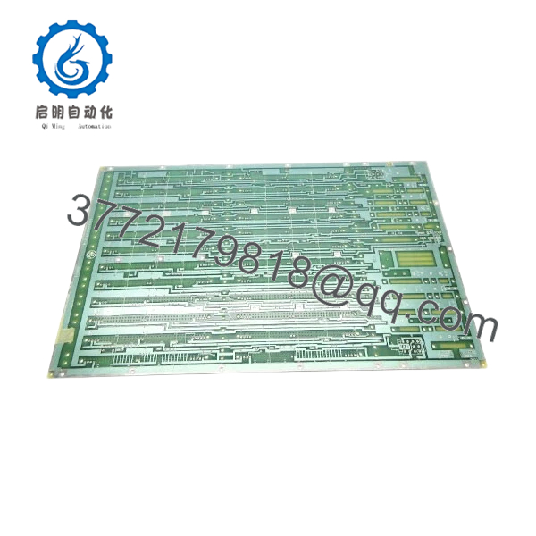
The GE DS3800XPEM1C1B is an excitation processing board used in the Mark IV Speedtronic turbine control system. It handles signal conditioning and interface functions related to generator excitation control.
In field applications, this board sits between excitation hardware and core control logic. Mark IV systems rely on discrete boards like this rather than integrated I/O modules, so exact model matching is mandatory. There is no abstraction layer—hardware behavior directly affects turbine stability and synchronization.
5. Installation & Configuration Guide
Stage 1: Pre-Installation Preparation (Estimated: 10 minutes)
- ⚠️ Safety First:
Shut down turbine, isolate excitation system, apply lockout/tagout. Wait minimum 5 minutes for discharge. - Tools Required:
ESD wrist strap, PH1 screwdriver, multimeter, wire labels, smartphone - Data Backup:
- Photograph board slot and wiring interfaces
- Record any jumper/DIP settings
- Document excitation system parameters
Stage 2: Removing the Old Module (Estimated: 5–10 minutes)
- Locate DS3800XPEM1C1B in the Mark IV rack.
- Label all wiring connections clearly.
- Disconnect connectors carefully—aged plastics can crack.
- Release retaining clips or screws.
- Pull the board straight out to protect backplane pins.
- Inspect rack connector for wear or contamination.
- ⚠️ Note: Keep the old module for reference until commissioning is complete.
Stage 3: Installing the New Module (Estimated: 10 minutes)
- Wear ESD protection.
- Verify exact model match (DS3800XPEM1C1B, suffix included).
- Configuration Clone (Critical):
- Replicate all jumper/DIP settings from original
- Insert into correct slot with proper alignment.
- Seat firmly using extractor handles.
- Reconnect all wiring exactly as labeled.
- Self-Checklist:
- Correct slot
- Jumpers match
- Wiring secured
- Board fully seated
Stage 4: Power-On & Testing (Estimated: 10–15 minutes)
- Pre-Power Check:
Verify no shorts on excitation signal paths. - Power-On Steps:
- Energize rack only (keep field excitation isolated initially).
- Observe board/system indicators.
- Check excitation feedback signals in control system.
- Gradually reintroduce excitation system.
- Validate stable voltage regulation and response.
- ⚠️ Troubleshooting Note:
- No excitation response → wiring or configuration mismatch
- Instability → signal scaling or grounding issue
- No comms → backplane seating problem

- DS3800XPEM1C1B
- DS3800XPEM1C1B
6. Frequently Asked Questions (FAQ)
Q1: Can this board be hot-swapped?
No. Mark IV systems are not designed for hot-swapping. You risk damaging the backplane or causing a turbine trip.
Q2: Is DS3800XPEM1C1B obsolete?
Yes. All Mark IV boards are discontinued. Availability depends on surplus inventory and refurbishment channels.
Q3: Is there a direct replacement in newer GE systems?
Not directly. Migration typically requires upgrading to Mark V or Mark VIe, which involves major engineering changes in hardware and software.
Q4: Will replacing this board affect turbine control logic?
Indirectly, yes. While logic resides elsewhere, incorrect excitation signals can destabilize voltage regulation and protection functions.
Q5: Why must the suffix (1C1B) match exactly?
Because hardware revisions may change signal timing, connector mapping, or component tolerances. Even small differences can cause system faults.
Q6: Why are surplus units priced lower than original OEM pricing?
Because they come from excess inventory or decommissioned systems. No OEM production, limited lifecycle support, and variable storage conditions.
SOP Quality Transparency
1. Inbound Inspection & Traceability
- Verified against GE part markings and revision codes
- Visual inspection: no corrosion, no rework, no connector wear
- Label integrity and PCB condition checked
2. Live Functional Testing
- Tested on Mark IV-compatible rack simulator
- Power-on validation and signal path verification
- Simulated excitation signal testing
- Continuous operation >24 hours with thermal monitoring
- Test reports available upon request
3. Electrical Parameter Testing
- Insulation resistance: >10 MΩ @ 500 V Megger
- Ground continuity verified
- Voltage rail stability confirmed
4. Firmware & Configuration Verification
- Hardware configuration (jumpers/DIPs) documented
- No firmware dependency typical for this board class
5. Final QC & Packaging
- QC sign-off with traceability
- ESD-safe packaging
- Industrial shock-protected boxing
Technical Pitfall & Survival Guide
❗ 1. Jumper / Configuration Mismatch
- Issue: Incorrect excitation behavior or no output
- Avoidance: Photograph and replicate all settings
- Reality: This is the #1 cause of failed replacements
❗ 2. Wrong Slot Installation
- Issue: No communication or system fault
- Avoidance: Match original slot exactly
- I’ve seen engineers waste hours troubleshooting a board in the wrong slot
❗ 3. Excitation System Sensitivity
- Issue: Small signal errors cause voltage instability
- Avoidance: Validate signals before full energization
- Real-world: Even minor scaling errors can trigger protection trips
❗ 4. Power Supply Margin Issues
- Issue: Aging PSU causes unstable operation
- Avoidance: Verify 5 V and 24 V rails under load
❗ 5. ESD Damage During Handling
- Issue: Latent failure after installation
- Avoidance: Always use grounded wrist strap
- I’ve personally seen boards fail hours after a clean startup due to static damage


