
 WhatsApp: +86 16626708626
 Email:
  Phone: +86 16626708626
Description
3. Key Technical Specifications
| Parameter | Value |
|---|---|
| Model | DS3826AS1D06AA |
| Brand | GE (General Electric) |
| Series | Mark IV (Speedtronic) |
| Product Category | Power Supply / Cell Stack Assembly |
| Product Type | Rack-mount DC-DC power conversion assembly |
| Weight | 24 lb (10.9 kg) |
| Input Voltage | Field configurable (typical Mark IV 125V DC input) |
| Output Voltages | Multiple DC rails (likely +5V, ±15V, +24V for Mark IV rack) |
| Mounting | Enclosed chassis, rack-mount or panel-mount |
| Cooling | Passive convection or forced air (depends on installation) |
| Operating Temp | 0 to +50°C (32 to 122°F) typical for Mark IV |
| Storage Temp | -40 to +85°C (-40 to 185°F) |
| GE Part Family | DS3826 (Mark IV Power Components) |
| Lifecycle Status | Obsolete — no factory support |
4. Product Introduction
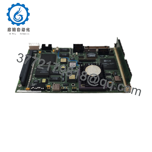
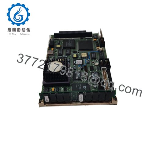
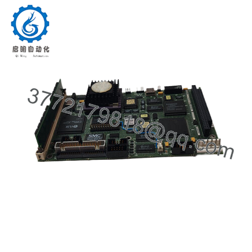
The GE DS3826AS1D06AA is a power supply cell stack assembly for the Mark IV Speedtronic turbine control system. This assembly houses the DC-DC conversion circuitry that takes raw field power (typically 125V DC from station batteries) and generates the regulated low-voltage DC rails (+5V, +15V, -15V, and +24V) required by Mark IV processor, I/O, and communication boards -1.
The DS3826AS1D06AA is not a plug-in board — it is an enclosed assembly designed for mounting in the lower section of a Mark IV rack or in a dedicated power distribution panel. It connects to the backplane via a multi-pin cable or bus bars. The “Cell Stack” designation indicates it likely contains multiple power conversion stages (cells) stacked in a single chassis. If your Mark IV rack is completely dead (no LEDs on any board), the NPSR board may be fine, and this assembly is the root cause.

- DS3826AS1D06AA
5. Installation & Configuration Guide
Estimated time for replacement by a qualified electrician: 60 minutes
Stage 1: Pre-Installation Preparation (15 minutes)
⚠️ Safety First: Notify operations of turbine shutdown. Verify steam supply locked out. Depressurize the hydraulic power unit (HPU). Lock out/tag out both AC and DC power sources to the Mark IV rack — this assembly operates at 125V DC, which is lethal. Wait 10 minutes for capacitors to discharge.
Tools Required:
- Multimeter with DC voltage capability (Fluke 87V or equivalent)
- Insulated screwdrivers (Philips and flathead)
- Nut driver or wrench set (for chassis mounting bolts)
- Wire labels or markers
- Smartphone for photos
- ESD mat (for handling any circuit boards inside the assembly — not required for the chassis itself)
- Flashlight
Data Backup & Documentation:
- Photograph the entire assembly, showing:
- All wiring connections (input and output terminals)
- Wire colors and terminal numbers
- Ground connections
- Any status LEDs or test points
- Document the assembly’s location in the rack (which slot or mounting position).
- Measure and record input voltage (should be 100-150V DC).
- If possible, measure output voltages at the backplane or at the assembly’s output terminals.
Stage 2: Removing the Old Assembly (20 minutes)
Step 1 (Power Verification): Use your multimeter to verify that input power is de-energized. Measure between input terminals — should read 0V DC. Measure from each input terminal to ground — should read 0V DC.
Step 2: Disconnect the input power cable (125V DC from station batteries or rectifier). Tag the cable with its source.
Step 3: Disconnect the output cables to the Mark IV backplane. Label each wire with its terminal designation.
Step 4: Remove any ground straps or bonding jumpers.
Step 5: Remove the mounting bolts or screws securing the assembly to the rack or panel. This assembly weighs 24 lb -1. Use two people or a support block.
Step 6: Pull the assembly straight out. Do not force — check for hidden screws or brackets.
Step 7: Place the old assembly on a workbench. Keep it for reference until the new unit is running.
Stage 3: Installing the New Assembly (20 minutes)
Step 1 (Unpacking): Unpack the new DS3826AS1D06AA on a clean, dry surface. Inspect for shipping damage (dents, loose components, broken terminals).
Step 2 (Verify Model): Confirm the label reads DS3826AS1D06AA exactly. Different suffixes may have different input voltage ranges or output configurations.
Step 3 (Mounting):
- Position the new assembly in the same location as the old unit.
- Secure with the original mounting bolts. Torque to manufacturer specification (if known) or hand-tight plus 1/4 turn.
- Ensure proper airflow clearance (no obstructions near ventilation slots).
Step 4 (Grounding): Reconnect all ground straps and bonding jumpers. A missing ground can cause electrical noise and unstable rack operation.
Step 5 (Wiring — Critical):
- Reconnect output cables exactly as photographed.
- Reconnect the input 125V DC cable (verify polarity — DC+ and DC-). Reverse polarity can destroy the assembly instantly.
- Double-check all connections before proceeding.
Self-Checklist:
- Assembly secured to rack (no movement)
- All ground connections made
- Input wiring verified (polarity correct)
- Output wiring matches photo
- No loose tools or debris inside the cabinet
Stage 4: Power-On & Testing (5 minutes)
Pre-Power Check (Important):
- With power still off, measure resistance between input DC+ and DC- terminals. Should be >10k ohms.
- Measure resistance from each output terminal to ground. Should be >1k ohm.
- Visually inspect for any pinched wires or exposed conductors.
Power-On Steps:
- Notify all personnel that you are applying power.
- Apply input power (125V DC) at the source breaker.
- At the assembly, measure input voltage (should be 100-150V DC).
- Measure output voltages at the assembly terminals or at the backplane:
- +5V DC: 5.0V ±0.25V
- +15V DC: 15.0V ±0.75V
- -15V DC: -15.0V ±0.75V
- +24V DC: 24.0V ±1.2V
- Observe the Mark IV rack LEDs. The NPSR board should show Power OK. Other boards should show Run or Standby LEDs.
- Connect the maintenance terminal. Verify no power supply-related faults.
⚠️ Troubleshooting:
| Symptom | Likely Cause | Action |
|---|---|---|
| No output voltage, input present | Internal fuse blown or component failure | Replace assembly. Do not attempt internal repair. |
| Output voltage low (e.g., +5V reads 3V) | Overload or regulator failure | Disconnect output cables. Measure again. If still low, replace assembly. |
| Output voltage high (e.g., +5V reads 7V) | Regulator failed shorted | Replace immediately. Overvoltage will damage all boards in the rack. |
| Assembly buzzes or hums loudly | Internal transformer or inductor loose | Normal at full load. If loud enough to hear across the room, replace preemptively. |
| Rack works but resets randomly | Output ripple too high or intermittent connection | Use oscilloscope to measure ripple. >100 mV on +5V indicates capacitor aging — replace assembly. |
| Overheating (case too hot to touch) | Overload or fan failure (if equipped) | Measure output currents. If within spec, replace assembly. |
6. Frequently Asked Questions (FAQ)
Q: What exactly is a “Cell Stack Assembly”?
A: In GE Mark IV terminology, a cell stack assembly is a multi-stage DC-DC power converter. It takes 125V DC input and generates multiple lower-voltage DC outputs through a series of conversion “cells” (stages). Each cell may be a switching regulator, linear regulator, or transformer-isolated converter. The DS3826AS1D06AA is the main power supply for the Mark IV rack — it feeds the NPSR board, which then distributes power to individual modules.
Q: Is the DS3826AS1D06AA a direct replacement for all Mark IV power supply assemblies?
A: No. There are multiple DS3826 variants. The “AS1D06AA” suffix indicates specific input/output characteristics. Do not assume that any DS3826 assembly will work in your rack. Verify your existing assembly’s label matches exactly. If you have a different suffix (e.g., AS1D04AA or BS1D06AA), contact us for compatibility verification. We can cross-reference GE part numbers.
Q: My Mark IV rack has an NPSR board. Do I also need this DS3826 assembly?
A: Yes, in most Mark IV configurations. The DS3826 assembly is the primary power supply — it converts 125V DC field power to intermediate DC voltages. The NPSR board then regulates and distributes power to individual slots. If your DS3826 fails, the entire rack loses power, and the NPSR will show no LEDs. Test by measuring input to the DS3826 (should be 125V DC) and output from the DS3826 to the backplane (should be present). If input present but no output, the DS3826 has failed.
Q: Can I repair my DS3826 assembly instead of replacing it?
A: We do not recommend field repair. The DS3826 contains high-voltage capacitors (125V DC input section) and custom magnetics. Replacing a failed capacitor without proper discharge can cause electric shock. Also, the multilayer PCB and surface-mount components are difficult to repair without a rework station. Most repair shops will simply replace the entire assembly. If you need a cost-effective solution, we offer new surplus units at competitive pricing.
Q: Why is this assembly so heavy (24 lb)?
A: The DS3826AS1D06AA contains a large isolation transformer, multiple inductors, and electrolytic capacitor banks. The transformer alone can weigh 10-15 lb. The steel chassis and internal heat sinks add the remaining weight. This is not a lightweight switching power supply — it’s a line-frequency (50/60 Hz) design typical of 1980s-1990s industrial equipment. Handle with care. Use two people for installation.
Q: My DS3826 works but hums loudly. Is that normal?
A: Some audible hum is normal — the transformer and inductors vibrate at 120 Hz (rectified DC ripple). However, if the hum has suddenly become louder or has changed pitch, suspect:
- Loose laminations in the transformer — This indicates aging. Replace preemptively.
- Capacitor failure — Dried-out capacitors cause higher ripple current, which increases magnetic noise.
- Mechanical resonance — Tighten mounting screws.
If the hum is audible from 10 feet away in a quiet room, replace the assembly.
Q: What’s your testing process for this assembly?
A: We test every DS3826AS1D06AA under load on a Mark IV test rack. Test sequence:
- Visual inspection (dents, corrosion, burnt smell, leaking capacitors)
- Case ground continuity check (ground pin to chassis: <0.5 ohm)
- Input power-up (125V DC from calibrated supply)
- No-load output voltage test (all rails within ±5%)
- Load test: Connect a Mark IV rack with NPSR and minimum I/O. Verify all rails stay within spec at full rack load.
- Ripple measurement (oscilloscope, <100 mV on +5V rail)
- Thermal imaging (no hot spots above 70°C at 25°C ambient)
- 24-hour burn-in with cycling (on for 8 hours, off for 1 hour, repeat)
Test report with voltage and ripple measurements available upon request.
Q: What’s the warranty on this obsolete assembly?
A: 1-year replacement warranty. Covers failure under normal operating conditions (0-50°C, 125V DC input ±10%). Does NOT cover damage from reverse polarity on input, lightning strikes, water ingress, physical damage (dents from dropping), or incorrect wiring. We cross-ship replacements within 24 hours for confirmed defects. Note that this assembly weighs 24 lb — return shipping costs for warranty claims are your responsibility unless the unit was DOA.


