
 WhatsApp: +86 16626708626
 Email:
  Phone: +86 16626708626
Description
⚡ Core Function and Positioning
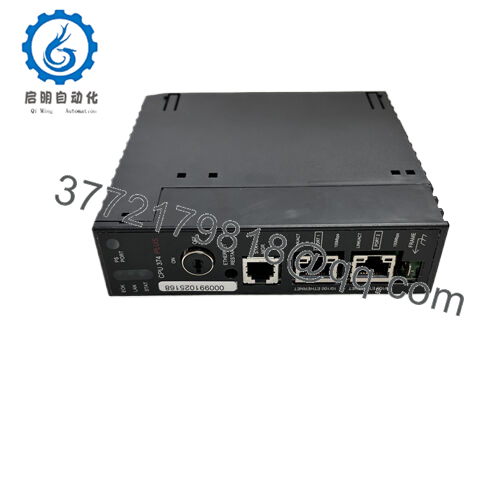
The GE IC693PWR322 is the vital component that powers the entire GE Fanuc Series 90-30 system. It is a high-capacity, switch-mode power supply designed to convert high-voltage AC utility power into the regulated DC power required by the PLC’s logic.
-
Role in System: The power supply occupies the dedicated Slot 0 (the leftmost slot) of the Series 90-30 chassis. It is the sole source of $5 \text{ VDC}$ logic power for the CPU, memory, and all I/O and communication modules installed on the backplane.
-
Universal Input: This module is highly versatile, accepting a universal AC input voltage ranging from $90 \text{ VAC}$ to $264 \text{ VAC}$ at a frequency of $47 \text{ Hz}$ to $63 \text{ Hz}$. This wide range eliminates the need for separate modules for $120 \text{ VAC}$ and $240 \text{ VAC}$ systems.
-
High Capacity: The primary distinction of the IC693PWR322 compared to the standard IC693PWR321 is its higher current capacity. This capacity makes it suitable for larger racks or those populated with many power-hungry modules, such as communication processors or high-density I/O.

- IC693CPU374-GU

🚀 Key Technical Specifications
The high-capacity design of the IC693PWR322 ensures it can reliably support fully loaded Series 90-30 systems, making it a robust choice for complex industrial automation.
| Parameter | Value |
| Model | IC693PWR322 |
| Brand | GE Fanuc / Emerson |
| Type | High-Capacity AC Power Supply Module |
| Input Voltage Range | $90 \text{ to } 264 \text{ VAC}$ |
| Output Voltage (Primary) | $5 \text{ VDC}$ |
| Output Current (Usable) | $8.0 \text{ Amperes}$ (significantly higher than standard models) |
| Max Power Output | $40 \text{ Watts}$ |
| Status Indicator | $5 \text{ VDC}$ OK LED |
| Slot Required | Slot 0 (Power Supply Slot) |
| System Platform | GE Fanuc Series 90-30 PLC |
🛠️ Installation and Maintenance
Proper installation and maintenance of the power supply are crucial for the stability of the entire control system.
Installation
-
Slot Placement: The module must be installed in the dedicated power supply slot (Slot 0) on the far left of the chassis.
-
Wiring: Connect the incoming AC line voltage (L1 and L2/N) to the designated screw terminals. A secure earth ground connection is required for safety and noise suppression.
-
Fuse: The module generally includes an internal fuse for protection against input overcurrent.
Maintenance and Diagnostics
-
LED Monitoring: The most important diagnostic tool is the $5 \text{ VDC}$ OK LED on the front face. A steady green light confirms stable operation. If the LED is off or flashing, the input power or the power supply itself may be faulty.
-
Thermal Management: As a high-capacity unit, the IC693PWR322 generates more heat. Ensure the control cabinet has adequate ventilation and that air vents on the chassis are not blocked. Excessive heat is the primary cause of premature power supply failure.1
-
Load Check: During system expansion, verify the total current draw of all modules (CPU, I/O, comms) does not exceed the $8.0 \text{ Ampere}$ capacity of the IC693PWR322.


