
 WhatsApp: +86 16626708626
 Email:
  Phone: +86 16626708626
Description
3. Key Technical Specifications
| Parameter | Value |
|---|---|
| Function | Exciter Attenuation Module (EXAM) |
| System Compatibility | GE EX2100 / EX2100e excitation systems |
| Input | Field voltage sensing via resistor network |
| Output | ±10 V DC, 4–20 mA control signals |
| Communication | Fiber-optic link to controller/EGDM module |
| Power Supply | 24 V DC |
| I/O Channels | Up to 13 channels |
| Redundancy | Supports dual system / up to 3 control sections |
| Mounting | Rack-mounted module (auxiliary/excitation cabinet) |
| Operating Temperature | 0 to +40°C typical |
| PCB Coating | Standard conformal coating |
| Weight | ~0.46–1 kg |
4. Product Introduction
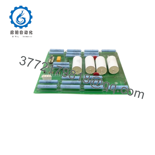
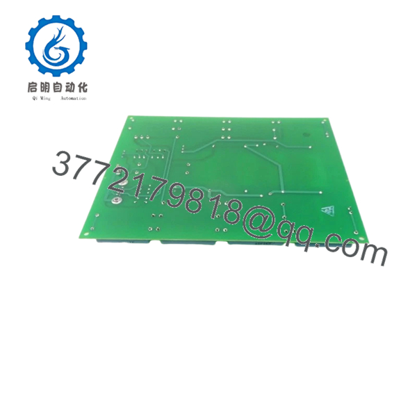
The GE IS200EXAMG1AAB is an Exciter Attenuation Module used in EX2100 and EX2100e excitation control systems. It attenuates high-voltage field signals and provides feedback for ground fault detection in generator excitation circuits.
In actual power plant deployments, this module works alongside the EGDM (Exciter Ground Detector Module) to detect leakage currents and protect the generator shaft from insulation failure. Compared to Mark IV/V systems, EX2100 introduces fiber-optic communication and distributed excitation control, but still depends on precise hardware pairing and correct wiring topology.
5. Installation & Configuration Guide
Stage 1: Pre-Installation Preparation (Estimated: 10 minutes)
- ⚠️ Safety First:
Shut down excitation system and turbine. Apply lockout/tagout. Wait 5–10 minutes for DC bus discharge (excitation systems can hold charge longer than standard PLC racks). - Tools Required:
ESD strap, insulated screwdriver, multimeter, labeling tags, smartphone - Data Backup:
- Record excitation parameters (field current, voltage scaling)
- Photograph wiring, especially EGDM connections and fiber link
- Document jumper/selector settings
Stage 2: Removing the Old Module (Estimated: 10 minutes)
- Locate module in excitation cabinet (not always in main control rack).
- Label all wiring including fiber-optic connections.
- Disconnect connectors carefully—fiber ports are fragile.
- Remove mounting hardware or release guides.
- Pull module straight out.
- Inspect connectors and fiber ends for contamination.
- ⚠️ Note: Do not touch fiber tips—contamination causes signal loss.
Stage 3: Installing the New Module (Estimated: 10–15 minutes)
- Wear ESD protection.
- Verify exact model: IS200EXAMG1AAB (revision must match if possible).
- Configuration Clone (Critical):
- Replicate jumper/selector settings
- Insert module into correct slot or mounting rail.
- Reconnect wiring and fiber-optic link (clean, click-fit)
- Secure module properly
- Self-Checklist:
- Fiber connected and clean
- Wiring correct
- Jumpers match
- Module secured
Stage 4: Power-On & Testing (Estimated: 15–20 minutes)
- Pre-Power Check:
Measure excitation circuit for residual voltage and shorts. - Power-On Steps:
- Power excitation system (controller first, then field devices).
- Verify communication with EGDM module.
- Check ground fault detection status.
- Monitor field current/voltage feedback signals.
- Perform controlled excitation test.
- ⚠️ Troubleshooting Note:
- No feedback → fiber link or EGDM mismatch
- False ground alarms → wiring or shielding issue
- No excitation response → signal attenuation path misconfigured

- IS200EXAMG1AAB
- IS200EXAMG1AAB
6. Frequently Asked Questions (FAQ)
Q1: Can this module be hot-swapped?
No. Despite some newer EX2100e variants supporting limited hot maintenance, this module should be treated as non-hot-swappable. Always isolate excitation power first.
Q2: Is IS200EXAMG1AAB obsolete?
It is not fully obsolete, but it is mature lifecycle hardware. GE still supports EX2100 in some regions, but lead times can be long. Surplus stock is commonly used.
Q3: What module works with this unit for ground detection?
It works with the EGDM (Exciter Ground Detector Module). The EXAM handles attenuation; EGDM performs measurement and alarm logic.
Q4: What happens if this module fails?
You lose reliable ground fault detection. Worst case, a ground fault goes undetected and causes rotor damage—this is not a module you ignore.
Q5: Why is fiber-optic connection used instead of copper?
Noise immunity. Excitation systems operate in high EMI environments. Fiber avoids false readings and signal corruption.
Q6: Why is pricing inconsistent across suppliers?
Because availability depends on surplus inventory, not ongoing production. Condition (new surplus vs refurbished) and test coverage drive price variation.
SOP Quality Transparency
1. Inbound Inspection & Traceability
- Verified GE labeling, part number, and revision code
- Visual inspection: no corrosion, no rework, intact fiber ports
- Connector integrity and coating condition checked
2. Live Functional Testing
- Tested on EX2100 excitation test rack
- Simulated field voltage attenuation and EGDM handshake
- Fiber-optic communication verified
- Continuous operation >24 hours with thermal monitoring
- Test report available upon request
3. Electrical Parameter Testing
- Insulation resistance >10 MΩ @ 500 V Megger
- Ground continuity verified
- Signal attenuation path verified
4. Firmware & Configuration Verification
- Hardware jumper settings documented
- No field-upgradable firmware dependency
5. Final QC & Packaging
- QC sign-off with traceable ID
- ESD-safe packaging
- Protective packaging for fiber connectors
Technical Pitfall & Survival Guide
❗ 1. Fiber-Optic Handling Damage
- Issue: Dirty or scratched fiber connectors → no communication
- Avoidance: Clean connectors, never touch ends
- Real case: I’ve seen a “failed board” that was just a dirty fiber tip
❗ 2. EGDM Pairing Mismatch
- Issue: EXAM installed but incompatible or faulty EGDM → false alarms
- Avoidance: Treat EXAM + EGDM as a functional pair
❗ 3. Ground Detection Misinterpretation
- Issue: False ground fault trips due to noise
- Avoidance: Maintain proper shielding and grounding
- Excitation systems are electrically noisy—don’t cut corners
❗ 4. Jumper Configuration Errors
- Issue: Incorrect attenuation scaling
- Avoidance: Copy settings exactly from old module
❗ 5. Power Isolation Mistakes
- Issue: Residual excitation voltage damages module
- Avoidance: Verify zero energy before handling
- I’ve seen engineers assume “PLC rules apply”—they don’t in excitation systems


