
 WhatsApp: +86 16626708626
 Email:
  Phone: +86 16626708626
Description
3. Key Technical Specifications
| Parameter | Value |
| Series | Mark VI Speedtronic |
| Board Type | Fiber Optic Serial Bridge (FOSB) |
| Revision | H1AAA |
| Optical Interface | ST-style fiber connectors |
| Data Format | Serial asynchronous/synchronous conversion |
| Isolation | Optical isolation for EMI/RFI immunity |
| Power Consumption | Approx. 5W |
| Mounting | Standard VME Rack/Carrier Slot |
| Operating Temp | 0 to 60 °C (32 to 140 °F) |
4. Product Introduction
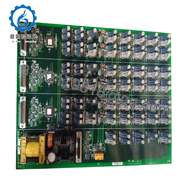
The GE IS200FOSBH1AAA is a high-performance Fiber Optic Serial Communication board within the Speedtronic Mark VI turbine control family. It is primarily utilized to bridge serial data over fiber optic links, providing essential electrical isolation between control racks and field devices or remote workstations.
In the high-EMI environment of a turbine deck, this board is critical for preventing ground loops and protecting sensitive control logic from lightning strikes or switching transients. By converting electrical signals to light, the FOSBH1AAA ensures reliable, noise-free communication across long distances that traditional copper cabling cannot safely achieve.
5. Installation & Configuration Guide
Stage 1: Pre-Installation Preparation
- ⚠️ Safety First: Ensure the Mark VI controller is in a stable state. Verify that the communication link being serviced is not actively controlling critical turbine parameters. Follow standard LOTO procedures for the control cabinet.
- Tools Required: Fiber optic cleaning kit (alcohol wipes/canned air), ESD wrist strap, PH1 screwdriver, fiber port dust caps.
- Inspection: Check the fiber optic cable ends for scratches or contamination. A single speck of dust can cause “Signal Loss” alarms.
Stage 2: Removing the Old Module
-
- Carefully disconnect the fiber optic cables from the ST connectors. Immediately place dust caps on both the cable ends and the board ports.
-
- Label the cables (TX and RX) to ensure they aren’t swapped during re-installation.
-
- Loosen the retention screws and pull the module straight out using the card edges or handles.
-
- ⚠️ Note: Do not bend the fiber cables beyond their minimum bend radius (typically 30 mm) to avoid internal glass fractures.
Stage 3: Installing the New Module
-
- ESD Prep: Connect your grounded wrist strap to the cabinet.
-
- Jumper Sync: Locate any jumpers on the IS200FOSBH1AAA and ensure they match the H1AAA revision defaults or your site-specific requirements.
-
- Seating: Slide the board into the VME rack slot. Apply firm, even pressure until the connectors mate with the backplane.
-
- Fiber Connection: Clean the fiber tips with an approved wipe. Remove the dust caps and click the ST connectors into place (push and twist).
- Self-Checklist: [ ] Fiber cleaned, [ ] Cables connected to correct ports (TX/RX), [ ] Board seated.
Stage 4: Power-On & Testing
-
- Power up the rack.
-
- Observe the status LEDs. You should see “Link” or “Activity” LEDs blinking if data is flowing.
-
- Use GE Toolbox to verify the “FOSB” module status. Check for “Loss of Signal” or “Framing Error” diagnostics.
-
- Troubleshooting Note: If the link does not establish, try swapping the TX and RX fibers at one end; “crossover” errors are the most common cause of commissioning delays.

- IS200FOSBH1AAA
- IS200FOSBH1AAA
6. Frequently Asked Questions (FAQ)
Q: Can I use this board in a Mark VIe system?
A: No. The IS200 series is designed for the VME-based Mark VI. The Mark VIe uses the IS215/IS220 series with different form factors and communication protocols (IONet).
Q: What do the “AAA” characters at the end of the part number mean?
A: These represent the revision level. “H1” is the hardware version, and “AAA” indicates the specific manufacturing artwork and firmware baseline. An “H1AAA” is generally interchangeable with other “H1” versions, but always verify your specific system configuration in the OEM manual.
Q: My fiber link is intermittent. Is the board failing?
A: Before replacing the board, clean the fiber connectors. 90% of fiber communication issues in industrial plants are caused by oil or dust contamination on the optical interface. If the problem persists after cleaning, the FOSBH1AAA might have a degrading laser diode or receiver.
Q: Is this board compatible with both gas and steam turbine controls?
A: Yes, as long as the system is a Mark VI Speedtronic. The FOSB function is independent of the turbine type; it handles the transport of data regardless of the underlying control logic.
Q: Why choose fiber over copper for these serial links?
A: In a power plant, the distance between the control room and the turbine enclosure can be hundreds of feet. Fiber provides total immunity to the massive electromagnetic interference (EMI) generated by generators and high-voltage lines, which would otherwise corrupt data on copper wires.


