
 WhatsApp: +86 16626708626
 Email:
  Phone: +86 16626708626
Description
Key Technical Specifications
| Parameter | Specification Value |
| Input Channels | 64 discrete inputs grouped into independent, software-interrogated bytes |
| Transition Detection | Change-of-State (COS) logic triggers VMEbus interrupts on positive or negative edges |
| Nominal Input Voltage | 24 VDC standard field voltage (jumper customizable for alternative ranges) |
| Form Factor | 6U Single-Slot VMEbus |
| Addressing Support | A16 or A24 short I/O space memory mapping |
| Interrupt Control | Programmable VMEbus interrupt vectors and request levels (IRQ 1 through 7) |
| Isolation Barrier | High-speed optical couplers separating field signals from VMEbus logic (up to 1,500 V) |
| Debounce Filtering | Jumper-selectable hardware low-pass filters for contact debounce protection |
| Current Consumption | +5 VDC (approx. 2.5 A maximum draw across the backplane) |
| Front Panel Connector | High-density multi-pin I/O headers for field wiring termination |
Product Introduction & Supply Chain Strategy
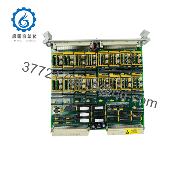
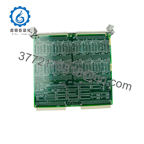
The GE VMIC VMIVME-1128 is a ruggedized, high-density 6U VMEbus discrete digital input card equipped with advanced Change-of-State (COS) detection circuitry. Rather than relying on continuous, processor-intensive software polling loop architectures, the VMIVME-1128 monitors all 64 input lines concurrently at the hardware layer. When a field sensor, limit switch, or trip relay changes its electrical state, the board’s internal logic generates an immediate VMEbus interrupt request. This event-driven functionality makes the module essential for Sequence of Events (SOE) recording, high-speed trip logging, and fault synchronization routines across power generation systems, turbine controls, and aerospace simulator frames.
Because this hardware has long passed its active manufacturing cycle and sits in full End-of-Life (EOL) status, it presents an extreme supply chain risk for facilities that run legacy real-time control networks. Procuring a verified New Surplus VMIVME-1128 module directly guards your system against the high failure rates and unpredictable performance metrics common to second-hand or poorly refurbished electronics. Opting for unissued, original OEM surplus ensures optimal optoisolator transition times and reliable capacitor performance, allowing inventory managers to keep a solid buffer stock on hand. This strategy drastically lowers Total Cost of Ownership (TCO) and mitigates the risk of catastrophic, multi-day stock-out events.

- VMIVME-1128
- VMIVME-1128
Installation & Configuration Guide
Stage 1: Pre-Installation (Prep & Safety)
- Completely power down the main VMEbus rack assembly. Secure the main circuit breakers using strict lock-out/tag-out (LOTO) safety compliance protocols.
- Put on a grounded static-dissipative ESD wrist strap tightly bonded to an unpainted, structural steel section of the rack housing.
- Carefully map out and document all physical jumper arrays on the surface of the failed board, focusing heavily on base memory addressing, interrupt request level selection (IRQ), and interrupt vector allocations.
- Duplicate these jumper placements exactly on the incoming New Surplus VMIVME-1128 card to ensure software integration compatibility.
Stage 2: Removal
- Loosen the upper and lower captive retaining screws anchoring the module front panel to the rails.
- Unfasten the high-density field wiring connectors from the front faceplate interface, securing the harnesses clear of adjacent guide tracks.
- Simultaneously pull both the top and bottom injector/ejector handles outward to break the backplane mechanical interface seal.
- Carefully extract the circuit board straight out along the chassis tracks, ensuring no component friction, and place it inside a static-shielding bag.
Stage 3: Installation (Clone & Seat)
- Inspect the backplane slot area with a light source to ensure that the J1 and J2 connector pin holes are free of contamination, dust, or alignment damage.
- Slide the newly configured VMIVME-1128 module smoothly into the targeted slot guide channels.
- Push the front panel inward firmly until the mechanical levers meet the chassis surface, then swing the levers completely inward to anchor the card connections firmly into the backplane arrays.
- Securely tighten the captive front-panel retaining screws to establish structural ground continuity across the chassis frame.
Stage 4: Power-On & Testing
- Re-terminate the high-density discrete field input cables to the front panel mating connectors.
- Clear the LOTO tags and power up the VME bus rack assembly.
- Verify that the card’s front panel fault status light turns on during initial power-up self-testing and then clears completely as the host operating system initializes.
- Execute your real-time software system diagnostics to trigger an interrupt simulation test pattern, confirming that the host processing node catches change-of-state registers across all 64 data bits.
Firmware/Software Versions & Upgrade Notes
The VMIVME-1128 operates as a hardware-mapped memory structure within standard VME short I/O address allocations (A16/A24 spaces). This register-driven topology means the board does not feature internal, field-flashable application firmware or programmable flash memory microcode.
⚠️ CRITICAL INTEGRATION WARNING: The change-of-state interrupt handling logic requires that your system’s Board Support Package (BSP) and real-time operating system (RTOS) drivers match the physical hardware timing profiles exactly.
If replacing an alternate digital input model generation with a COS-enabled VMIVME-1128 card, your software environment must be correctly configured to clear the interrupt flag registers immediately following an interrupt service routine (ISR) cycle. Leaving these transition registers uncleared will cause the board to continuously hold the VMEbus interrupt line low, which can freeze the host CPU node during subsequent system processing cycles.
Frequently Asked Questions (FAQ)
What is the practical operational benefit of Change-of-State (COS) detection?
Standard digital inputs require the system processor to constantly poll the memory space to check for state changes, which consumes significant processing bandwidth. COS detection uses hardware logic on the VMIVME-1128 to monitor inputs and instantly trigger a VMEbus interrupt request the moment a change occurs. This approach reduces CPU overhead and ensures microsecond-level accuracy for sequence-of-events capturing during system faults.
Can this digital input card be hot-swapped while the VME chassis is running?
No. The standard VMEbus backplane specifications utilized across the VMIVME-1128 family do not allow for live board insertion or removal. Attempting to pull or slide this card into a live, powered rack can trigger transient voltage spikes across the shared data lines, which risks destroying the board’s onboard VME logic and interrupting operation for adjacent cards in the rack.
How is the discrete field signal excitation voltage range configured on this board?
The input threshold levels are determined by factory-installed input resistor networks combined with physical jumper locations on the internal PCB. While 24 VDC is the standard configuration for industrial applications, always confirm that your field loop voltages align with the jumper settings specified on your plant’s electrical print before applying external power.
What parameters does your “New Surplus” inspection verify before shipment?
Every New Surplus VMIVME-1128 module undergoes rigorous inbound physical and electrical inspections in an ESD-controlled workspace. We check for perfect mechanical pin alignment on the J1/J2 backplane blocks, confirm that all trace structures and solder fields are free from aging or thermal oxidation, and verify that the onboard jumper sets match the required factory configuration baselines.
Are the onboard low-pass filters adjustable?
Yes. The module includes internal hardware low-pass filters to manage contact bounce from mechanical relays or field switches. These bounce profiles can be configured or bypassed using the board’s jumper settings, allowing you to match the system’s response times to either mechanical field contacts or high-speed, solid-state electronic signals.


