
 WhatsApp: +86 16626708626
 Email:
  Phone: +86 16626708626
Description
3. Key Technical Specifications
| Parameter | Value |
|---|---|
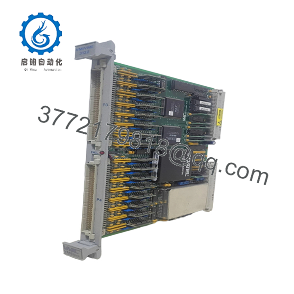
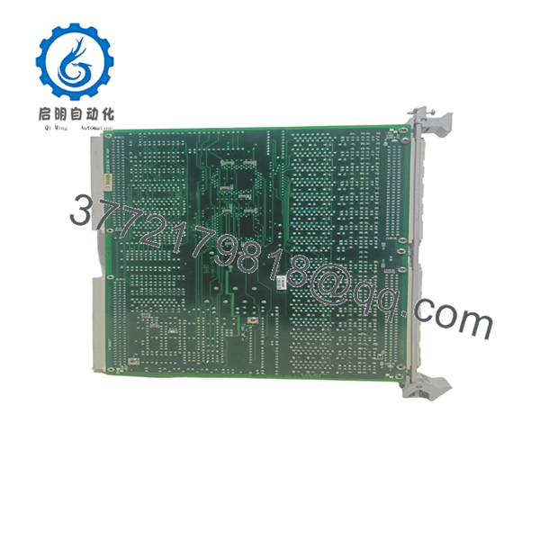
| Model Number | VMIVME 3122 (332-013122-000-A) |
| Manufacturer | GE Fanuc / VMIC |
| Product Type | Analog Scanning and Digitizing Input Board |
| Bus Interface | VMEbus |
| ADC Resolution | 16-bit |
| Input Channels | 16, 32, or 64 differential/single-ended (configuration dependent) |
| Conversion Rate | Up to 100 kSPS (High Performance Version) |
| Input Ranges | ±2.5 V, ±5 V, ±10 V, 0–5 V, 0–10 V |
| Programmable Gain | x1 or x10 |
| Buffer Memory | 1,024-word dual-port buffer |
| Trigger Modes | Software, External, Interval Timer |
| Scan Modes | Autoscan, Single Scan, Random Access |
| Address Space | A16, A24, A32 |
| Operating Temperature | 0 °C to +65 °C |
| Storage Temperature | -40 °C to +85 °C |
| Power Requirement | 5 VDC, up to 7 A |
| Board Format | 6U VME Eurocard |
| Product Status | Discontinued by OEM |
The VMIVME-3122 is a high-resolution VMEbus analog input board designed for data acquisition, process control, factory automation, machine monitoring, and laboratory instrumentation. It supports up to 64 analog input channels with 16-bit conversion accuracy and programmable gain control.
4. Product Introduction
The GE VMIVME 3122 (332-013122-000-A) is a VMEbus-based 16-bit analog input module designed for high-density data acquisition applications. The board continuously scans and digitizes analog signals from field devices such as thermocouples, RTDs, strain gauges, and process transmitters while minimizing host CPU loading through onboard buffering and timing functions.
In legacy GE Fanuc, VMIC, and embedded VME control systems, this board was commonly selected because it combines 64-channel acquisition capability, programmable gain, multiple triggering modes, and up to 100 kSPS conversion speed on a single-slot VME platform. For facilities maintaining existing VME infrastructure, it remains a practical replacement option when minimizing system redesign is a priority.

- VMIC VMIVME 3122 332-013122 000 A
- VMIC VMIVME 3122 332-013122 000 A
5. Installation & Configuration Guide
Stage 1: Pre-Installation Preparation (10 Minutes)
⚠️ Safety First
- Notify operations and maintenance personnel.
- Place the process in a safe operating state.
- Apply Lockout/Tagout (LOTO).
- Remove power from the VME rack.
- Wait at least 5 minutes for power supply discharge.
Tools Required
- ESD wrist strap
- PH1 screwdriver
- Fluke 115 multimeter
- Label maker or wire tags
- Smartphone camera
- VME rack documentation
Data Backup
- Export controller configuration files.
- Record slot location.
- Save application software configuration.
- Photograph all connectors.
- Photograph jumper blocks and configuration switches.
- Document scan rates and gain settings.
Stage 2: Removing the Old Module (5 Minutes)
- Remove front-panel retaining screws.
- Label all connected cables.
- Disconnect I/O connectors carefully.
- Release extraction levers.
- Pull the board straight out.
⚠️ Note
Do not discard the old board until the replacement has completed operational testing.
Inspection Checklist
- No bent VME backplane pins
- No connector corrosion
- No loose card guides
- No conductive dust accumulation
Stage 3: Installing the New Module (10 Minutes)
Steps
- Wear ESD protection before touching the board.
- Verify exact model number:
- VMIVME 3122
- 332-013122-000-A
- Configuration Clone (Critical)
- Match all jumpers.
- Match gain settings.
- Match channel configuration.
- Insert board into card guides.
- Seat fully into VME backplane.
- Tighten front-panel hardware.
- Reconnect field connectors.
Self-Checklist
- Model matches
- Jumpers duplicated
- Wiring secured
- Board seated fully
- Front panel secured
Stage 4: Power-On & Testing (15 Minutes)
Pre-Power Check
- Verify +5 VDC supply.
- Check for short circuits.
- Inspect grounding system.
Power-Up Procedure
- Energize VME rack.
- Observe board status LED.
- Verify controller recognizes the board.
- Confirm VME address mapping.
- Verify channel scan operation.
- Simulate several analog inputs.
- Validate scaling and gain settings.
- Confirm buffer updates correctly.
⚠️ Troubleshooting Note
- Continuous fault indication: Check address conflicts.
- Missing channels: Verify connector seating.
- Communication faults: Confirm VMEbus addressing.
- Incorrect readings: Verify gain configuration and input range selection.
SOP Quality Transparency
1. Inbound Inspection & Traceability
Every VMIVME 3122 board undergoes:
- OEM label verification
- Serial number recording
- Anti-counterfeit inspection
- Visual inspection for:
- Corrosion
- Rework marks
- PCB discoloration
- Connector damage
- Accessory verification when available
2. Live Functional Testing
Testing is performed using a genuine VMEbus test chassis.
Procedures include:
- Power-on verification
- LED status confirmation
- VMEbus communication testing
- Analog input simulation
- Gain switching verification
- Buffer memory verification
- Continuous operation exceeding 24 hours
- Thermal monitoring
A formal test report can be provided upon request.
3. Electrical Parameter Testing
- 500 V Megger insulation test (>10 MΩ)
- Ground continuity verification
- Supply current measurement
- Input channel validation
4. Firmware & Configuration Verification
- Hardware revision documented
- Jumper configuration recorded
- Configuration photographs archived
5. Final QC & Packaging
- QC inspector approval
- Anti-static ESD bag
- Shock-resistant packaging
- Heavy-duty export carton
- QC Passed label with inspection date
Test photos and operational videos are available upon request.
Technical Pitfall & Survival Guide
❗ Firmware Revision Mismatch
VME systems often contain hardware from multiple upgrade cycles.
I’ve seen replacement boards installed successfully, only to discover application software expected a slightly different hardware revision.
Avoidance:
- Record existing board revision.
- Match revision whenever possible.
- Verify driver compatibility before shipment.
❗ DIP Switch / Jumper Misconfiguration
This is the most common rookie mistake, but experienced technicians still get caught by it.
Take a picture before you pull it. I can’t stress this enough.
Avoidance:
- Photograph every jumper.
- Record gain settings.
- Document address selections.
❗ Terminal Block / Wiring Incompatibility
Never assume connector pinouts are identical between revisions.
I’ve encountered systems where replacement boards physically fit but used different cable assemblies.
Avoidance:
- Verify connector part numbers.
- Check wiring diagrams.
- Confirm shield grounding points.
❗ Power Draw Specifications
VME racks can run surprisingly close to power limits.
A new acquisition board may operate correctly alone but cause instability once the entire rack is loaded.
Avoidance:
- Calculate total rack current.
- Maintain at least a 20% power reserve.
- Verify cooling airflow requirements.
❗ Electrostatic Discharge (ESD)
One winter shutdown, I watched a technician remove a VME board without grounding himself.
The board passed inspection, powered up, and failed two days later.
Avoidance:
- Wear a grounded wrist strap.
- Use ESD-safe workstations.
- Store boards in anti-static packaging.
Keep these checks in mind and you’ll save yourself 90% of typical rework time.
6. Frequently Asked Questions (FAQ)
Q1. Can I hot-swap the VMIVME 3122?
No.
The VMIVME 3122 was designed for standard VMEbus systems and should not be removed under power. Doing so risks backplane damage, bus faults, and data corruption.
Q2. Is the VMIVME 3122 obsolete?
Yes.
The board belongs to the legacy VMIC VMEbus product family and is no longer in active OEM production. Most available inventory comes from surplus stock or tested refurbished units.
Q3. Is 332-013122-000-A the same as VMIVME-3122?
Generally yes.
The VMIVME-3122 is the base product family. The 332-013122-000-A suffix identifies a specific hardware configuration or ordering option. Always verify the full part number before purchasing.
Q4. Will I lose my application software if I replace the board?
No.
Application logic normally resides in the host CPU or controller, not in the analog input board. However, configuration parameters and scaling data should always be backed up before replacement.
Q5. What devices can connect to this module?
Common inputs include:
- Thermocouples
- RTDs (through conditioning hardware)
- Strain gauges
- Pressure transmitters
- Process voltage signals
The board was specifically designed to work with VMIC signal conditioning hardware.
Q6. Why is this module still in demand?
Many power plants, aerospace test systems, defense platforms, and industrial facilities continue operating VMEbus infrastructure.
Replacing a single failed board is often far less expensive than redesigning an entire VME control system.
Q7. What condition is typically available?
Current market inventory generally falls into one of these categories:
- New Original (New Surplus)
- Factory-Sealed Surplus
- Refurbished (Tested)
- Removed Working Spare


