
 WhatsApp: +86 16626708626
 Email:
  Phone: +86 16626708626
Description
3. Key Technical Specifications
- Input Voltage: 24 VDC
- Communication Protocols: Modbus, Profibus, Ethernet
- Analog Inputs: 4–20 mA, 0–10 V
- Digital Inputs: 8 channels
- Digital Outputs: 4 channels
- Control Modes: PID, ON/OFF logic
- Operating Temperature: -40°C to +85°C
- Communication Ports: RS485 + Ethernet
- Physical Form Factor: Compact industrial module (~field controller class)
- System Role: Master controller coordinating slave I/O modules
4. Product Introduction
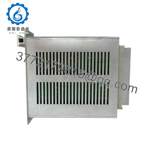
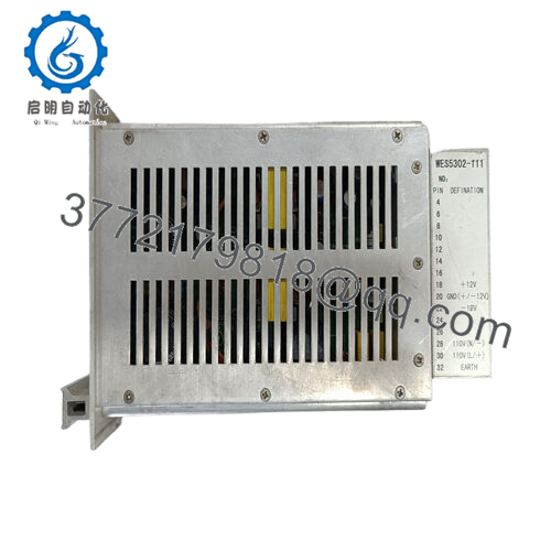
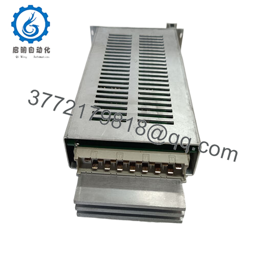
The GE WES5302-111 is a field controller master unit used in industrial automation systems for real-time control of sensors, actuators, and distributed I/O modules. It typically operates as the central coordination node in turbine control or process automation environments.
This module integrates multi-protocol communication (Modbus, Profibus, Ethernet) and mixed analog/digital I/O handling. It is deployed in legacy GE-based control architectures where deterministic control and system stability are prioritized over modern PLC modular expansion.

- WES5302-111
5. Installation & Configuration Guide
Stage 1: Pre-Installation Preparation
⚠️ Safety First: Shut down the control system, apply LOTO, and verify zero voltage on the 24 VDC supply rails. Wait at least 5 minutes for full discharge.
Tools Required: ESD wrist strap, insulated screwdriver, multimeter, terminal labels, and a camera for wiring documentation.
Data Backup:
- Record all I/O mapping and control logic configuration
- Document communication parameters (Modbus/Profibus node IDs)
- Photograph all terminal wiring and grounding points
Stage 2: Removing the Old Module
- Disconnect 24 VDC power supply
- Label all field I/O and communication cables
- Disconnect RS485 / Ethernet lines carefully
- Release mounting clips or rack lock mechanism
- Remove module straight out without lateral force
- Inspect connector pins for oxidation or burn marks
⚠️ Note: These modules are sensitive to static discharge and connector misalignment—handle only with grounded protection.
Stage 3: Installing the New Module
- Verify exact model match: WES5302-111
- Apply ESD grounding strap
- Mount module into DIN rail or control rack position
- Secure locking mechanism
- Reconnect all I/O wiring according to original labels
- Reconnect communication buses (RS485 / Ethernet)
Self-Checklist:
- Power input polarity verified
- I/O wiring matches original configuration
- Communication addresses confirmed
- Grounding properly connected
Stage 4: Power-On & Testing
- Apply 24 VDC power only
- Observe system LED indicators (POWER / STATUS / FAULT)
- Verify communication link via Modbus or Ethernet tool
- Check analog input stability (4–20 mA loop)
- Validate digital I/O switching response
- Run control loop test (PID / ON-OFF mode)
⚠️ Troubleshooting Note:
- No boot / no LEDs → incorrect power input or internal failure
- Communication loss → wrong protocol or node mismatch
- Erratic outputs → grounding issue or analog scaling mismatch
Estimated commissioning time: 20–40 minutes depending on system complexity
6. Frequently Asked Questions (FAQ)
Is the WES5302-111 hot-swappable?
Generally no. Most field controller implementations require full power isolation before removal to avoid I/O corruption and bus instability.
What systems use this module?
It is typically found in GE-based turbine control and distributed industrial automation systems where legacy field controllers manage mixed analog and digital signals.
Is this a PLC or a DCS module?
It behaves closer to a DCS field controller, coordinating distributed I/O rather than acting as a standalone PLC CPU.
Can it integrate with modern SCADA systems?
Yes, through Ethernet or Modbus TCP interfaces, but integration depends on gateway configuration and protocol bridging.
What is the most common failure mode?
Field data typically shows:
- Power supply instability at 24 VDC
- Communication bus mismatch (RS485 addressing)
- Environmental stress (temperature cycling)
- Connector oxidation in harsh environments
Is this product still manufactured by GE?
No. It is generally sourced through industrial surplus and legacy system support channels.
Can it replace a PLC CPU?
Not directly. It is a system-level controller module, not a general-purpose PLC CPU replacement.



