
 WhatsApp: +86 16626708626
 Email:
  Phone: +86 16626708626
Description
3. Key Technical Specifications
- Application: Industrial control systems (power, rail, infrastructure)
- Board Type: Plug-in control / interface PCB
- Functionality: Signal conditioning, logic handling, subsystem interface
- Backplane Interface: Proprietary rack connection
- Power Supply: System-fed (commonly 24 V DC or ±15 V rails depending on design)
- I/O Type: Mixed digital/analog (project-specific wiring)
- Connector Type: Edge connector / terminal blocks (variant dependent)
- Operating Temperature: 0 to +50 °C typical
- Mounting: Rack or cabinet-mounted system
- Revision Identifier: P-1206
4. Product Introduction
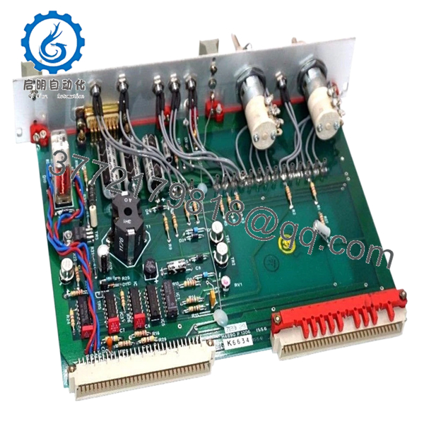
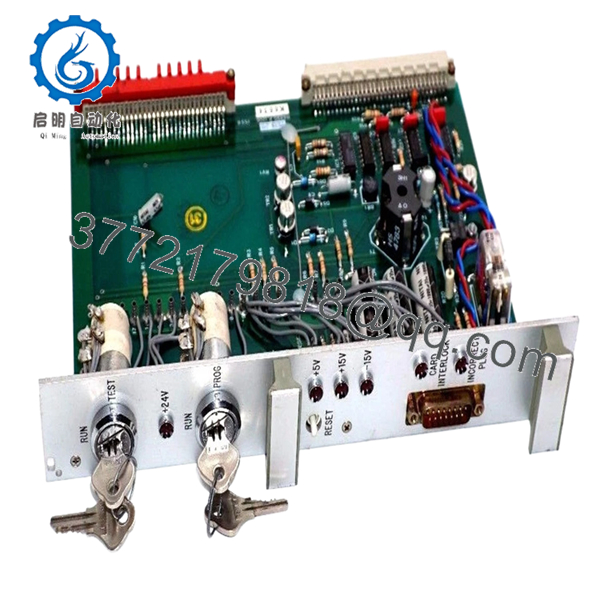
Harland Simon H4890-P-1206 is a legacy control PCB used in engineered industrial control systems, often deployed in critical infrastructure such as power plants, transport systems, and process facilities. These boards are typically part of custom-built control racks rather than standardized PLC platforms.
From field experience, the main challenge is not replacing the board itself, but ensuring exact compatibility with the existing system configuration. Even small differences in revision or wiring assumptions can lead to incorrect system behavior.
5. Installation & Configuration Guide
Stage 1: Pre-Installation Preparation (Estimated: 20 minutes)
- ⚠️ Safety First: Place system in a safe state. Lock out power sources and verify outputs are de-energized. These systems often control live equipment.
- Tools Required: ESD strap, multimeter, screwdriver, labeling tags, smartphone (for detailed photos).
- Data Backup:
- Photograph all wiring and terminal layouts
- Record system alarms and operational state
- Capture jumper/DIP configurations
Stage 2: Removing the Old Module (Estimated: 10–15 minutes)
- Identify exact board location in rack.
- Label all wires clearly — do not rely on memory.
- Disconnect wiring carefully to avoid terminal damage.
- Release retaining clips or screws.
- Pull board straight out along guide rails.
- ⚠️ Note: Retain the original board for configuration reference.
Stage 3: Installing the New Module (Estimated: 15 minutes)
- Apply ESD protection. Confirm exact model H4890-P-1206.
- Compare jumper/DIP settings with the original board.
- Insert board evenly into rack guides.
- Secure with mounting hardware.
- Reconnect wiring using labels and photos.
- Self-Checklist:
- Full part number matches
- Jumper/DIP settings replicated
- Wiring restored correctly
- Board securely mounted
Stage 4: Power-On & Testing (Estimated: 20–30 minutes)
- Pre-Power Check: Verify no shorts on supply rails using a multimeter.
- Power-On Steps:
- Restore system power.
- Observe system indicators and alarms.
- Verify board functionality (if monitored).
- Test associated I/O signals.
- Confirm system stability.
- ⚠️ Troubleshooting Note:
- No response → jumper mismatch or incorrect part
- Incorrect outputs → wiring or pinout differences
- Intermittent faults → poor backplane contact
6. Frequently Asked Questions (FAQ)
Q1: Is H4890-P-1206 interchangeable with other H4890 variants?
❗ No.
The suffix (P-1206) defines the exact configuration. I’ve seen near-identical boards behave differently due to small circuit or logic changes.
Q2: Is this a standard PLC module?
No. This is part of a custom-engineered control system, not a modular PLC under IEC 61131 standards.
Q3: Can this system be upgraded to a modern PLC?
Only through a full migration:
- I/O remapping
- Control logic rewrite
- Panel redesign
This is a major engineering project.
Q4: Why is documentation limited?
These systems were delivered as project-specific solutions. Documentation is typically retained on-site or by the original integrator.
Q5: What is the biggest installation risk?
❗ Configuration mismatch.
Incorrect jumper settings or wiring errors cause most failures — not the hardware itself.
Q6: Why does pricing vary widely?
Supply is scarce:
- Decommissioned systems
- Spare inventory
Condition varies — always request test verification.
Q7: Can unused boards fail over time?
Yes. Component aging (especially capacitors) can cause failures even if the board was never deployed.

- H4890-P-1206
- H4890-P-1206
SOP Quality Transparency (Inspection & Testing Process)
1. Inbound Inspection & Traceability
- Verified model: H4890-P-1206
- PCB markings and identifiers checked
- Visual inspection (no corrosion, no rework marks)
- Connector and solder joint integrity verified
2. Live Functional Testing
- Tested in compatible rack or simulated environment (if available)
- Power-on behavior verified
- Signal I/O simulation performed where feasible
- 24-hour continuous operation test
- Test report generated (available upon request)
3. Electrical Parameter Testing
- Insulation resistance >10 MΩ @ 500 V
- Ground continuity verified
- Power rail stability measured using Fluke 115
4. Firmware & Configuration Verification
- Revision P-1206 confirmed
- Jumper/DIP configurations documented
- Photographic records maintained
5. Final QC & Packaging
- QC sign-off with traceability
- ESD-safe sealed packaging
- Shock-protected industrial carton
- QC Passed label with inspection date
Test photos and videos available upon request.
Technical Pitfall & Survival Guide
1. Part Number Mismatch
❗ Most common issue.
H4890 looks correct, but wrong suffix — system behaves incorrectly.
Avoidance: Match full part number exactly.
2. Jumper / DIP Switch Misconfiguration
❗ Happens constantly.
One incorrect setting can alter signal paths.
Avoidance: Take clear photos before removal and replicate exactly.
3. Wiring Errors
❗ Especially in aging panels with poor labeling.
I’ve seen swapped wires cause unintended outputs.
Avoidance: Label everything before disconnecting.
4. Power Supply Instability
Older systems often have degraded power rails.
Avoidance: Measure voltage levels before installing replacement.
5. ESD Damage
❗ Silent failure risk.
Board may pass initial tests but fail under load.
Avoidance: Use grounded wrist strap and ESD-safe workspace.


