

 WhatsApp: +86 16626708626
 Email:
  Phone: +86 16626708626
Description
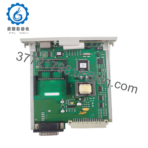
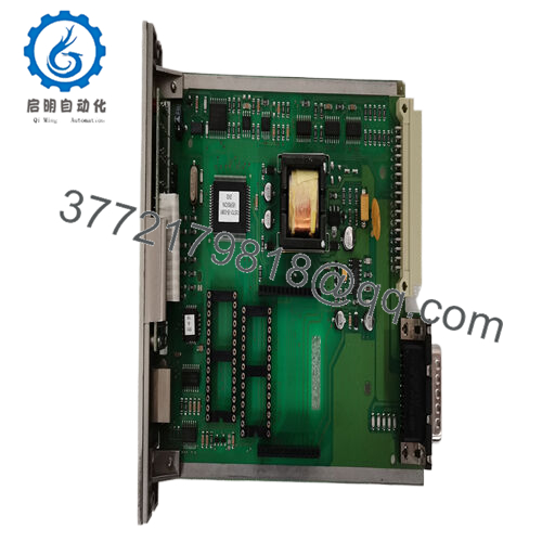
Product Model: 05701-A-0361
Product Brand: Honeywell (Zellweger / Analytics)
Product Series: System 57 / Engineering Card
Key Features:
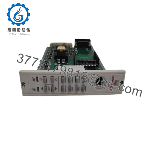
- Provides full setup, calibration, diagnostic, and maintenance functions for each channel card in a System 57 rack.
- Front-panel tactile push buttons to check alarm levels, set spans, zero, inhibit, etc.
- Real-time on-board clock, storing calibration history and reminders for overdue calibration.
- Operates from 18–32 VDC, consuming ~1.5 W

- 05701-A-0361
Product Role & System Fit
In Honeywell’s System 57 / Analytical / Control platform (often used in gas detection, process analytics, safety / monitoring systems), each analog or channel card needs calibration, configuration, diagnostics, and periodic maintenance. The 05701-A-0361 Engineering Card serves as the interface and control module for those tasks.
Physically plugged into a System 57 rack, this card gives technicians access to each channel card via push-button controls and LED indicators. With it, users can set zero, span, alarm thresholds, inhibit channels, view diagnostics, and monitor performance parameters — all in situ. Reseller descriptions call it “engineering card provides full maintenance and set up facilities for each channel card.”
It also embeds a real-time clock to log calibration dates and trigger reminders when calibration is due. This helps maintain compliance in regulated environments and ensures that channel performance doesn’t drift unmonitored.
In sum, 05701-A-0361 is the “control console” module inside a System 57 system—without it, many calibration or setup tasks would require external tools or complicated bypasses.
Technical Features & Benefits
Though not a measurement card itself, the 05701-A-0361 has several functional and design elements that deserve attention from engineers and maintenance staff.
Front Panel & User Interface
- The card has tactile feedback push buttons (Up / Down / Accept / Reject / Print combinations) to navigate through configuration menus and perform adjustments.
- LEDs indicate state such as Power On, Unlocked / Locked, and error or alarm states.
- The interface allows channel selection, alarm level checks, span/zero setting, clock control, calibration checks, and command abort.
Power & Consumption
- The card runs from 18 V to 32 V DC supply voltage.
- Typical power consumption is ~1.5 W.
Physical Dimensions & Weight
- One listing gives dimensions of 132 mm × 25 mm × 170 mm (height × width × depth).
- The weight is quoted ~ 152 g.
Functionality & Diagnostics
- It supports security-protected operation, meaning the configuration / calibration functions are not freely modifiable without proper authority or password lock.
- The card offers features like command accept / abort, allowing operations to be rolled back.
- It retains calibration history, enabling technicians to review past calibration dates, changes, and set reminders for due calibration.
Because this card integrates with channel cards, it must be compatible with the System 57 bus, signal protocols, and calibration routines.
Installation & Maintenance Insights
Here are practical tips when working with the 05701-A-0361 Engineering Card in the field.
Rack Insertion & Handling
- Always power down or isolate the rack before removing or inserting the engineering card to avoid backplane or bus damage.
- Align card edge connectors carefully; forcing them misaligned can damage contacts.
- Use proper ESD precautions — the board contains clock, memory, and likely programmable logic elements sensitive to static.
Power Wiring & Voltage
- Ensure the DC supply to the card is within 18–32 VDC with sufficient current margin (even though the card only draws ~1.5 W).
- Use properly rated wiring with good shielding and grounding to avoid noise injection into the control / diagnostic circuits.
Commissioning & Calibration
- After installation, verify the front panel buttons and LEDs are functioning.
- Use the engineering card to read baseline measurements from channel cards (zero, span, alarms) before full operation.
- Ensure the on-board clock is set correctly; calibrations and time stamps depend on it.
- If the engineering card supports printing or reporting calibration status, verify that output works.
Diagnostics & Fault Handling
- If the card’s LEDs show error or flickering, refer to the System 57 diagnostic manual for codes (e.g. configuration mismatch, memory error).
- If channel cards are not responding or calibration functions fail, check that the engineering card’s bus connections, firmware version, and voltage supply are correct.
- Keep the card’s firmware or revision label recorded; mismatched versions (with the system controller or channel cards) may lead to incompatibility.
Spare Strategy
- Given the complexity and importance of this card in calibration and maintenance, it’s prudent to maintain a spare 05701-A-0361 (or equivalent model).
- Ensure the spare is the same revision (or compatible variant) and test it off-line before insertion.
- Backup all calibration data before swapping to avoid losing setup history.
Technical Specifications Table
Here is a compact summary (from compiled sources) for your reference:
| Specification | Value / Range | Remarks / Sources |
|---|---|---|
| Model | 05701-A-0361 | |
| Module Type | Engineering / Control / Interface Card | System 57 maintenance / setup card |
| DC Supply Voltage | 18 – 32 VDC | |
| Power Consumption | ~1.5 W | |
| Dimensions (HxWxD) | ~132 mm × 25 mm × 170 mm | |
| Weight | ~152 g | |
| User Interface | Push buttons, LEDs | |
| Clock & Memory Functions | On-board real-time clock, calibration history | |
| Security Protection | Supported | |
| Compatibility | System 57 rack / channel cards |
Use this table carefully — some specs are from reseller listings and may differ slightly in your specific hardware version.
Related Modules / Ecosystem
- Channel Cards / Control Cards — The engineering card interacts with individual channel cards (e.g. analog input, output, sensor drive) in a System 57 rack.
- Modbus / Interface Expansion Options — The engineering card design supports plug-in Modbus interface kits (e.g. via EPROM / RAM expansions) to add RS-422/485 or RS-232 external communication.
- System 57 Spares / Accessories — Other modules like 05701-A-0282, 05701-A-0385, calibration / output cards, etc., all fit into the same System 57 family.


