
 WhatsApp: +86 16626708626
 Email:
  Phone: +86 16626708626
Description
Key Technical Specifications
| Parameter | Value |
|---|---|
| Manufacturer | KOKUSAI Electric |
| Board Part Numbers | KOMS-A2 / CXP-544A |
| Form Factor / Type | Proprietary Industrial Bus Motherboard |
| System OS / Environment | MS-DOS / Real-time Embedded Control OS |
| Onboard Memory | Integrated system RAM sockets (expansion memory SIMM/DIMM supported) |
| Communication / Ports | RS-232C / RS-485 Serial, Parallel/Centronics, Bus Ribbon Headers |
| Power Requirements | Regulated DC inputs (+5V, +12V, -12V via backplane / power header) |
| Operating Temperature | 0 °C to 55 °C (32 °F to 131 °F) |
Overview & Hardware Strategy
The KOKUSAI KOMS-A2 / CXP-544A is an industrial CPU motherboard board assembly designed for KOKUSAI semiconductor tools, thermal processing equipment, and precision industrial automation systems. It functions as the central processing engine that manages timing sequences, temperature/gas flow loop commands, and communications between human-machine interfaces (HMIs) and field I/O racks.
Because legacy semiconductor and industrial fabrication lines rely heavily on custom architecture boards like the CXP-544A, a component failure on the motherboard can bring entire production runs to a halt. Sourcing tested original replacement boards ensures full signal-level compatibility without needing costly retrofit programs or hardware redesigns.
Board Installation & Replacement Steps
1
Stage 1: System Shutdown & ESD Control
Safety & Isolation
1.Stage 1: System Shutdown & ESD Control:Safety & Isolation.
Power down the machine tool and isolate the main electrical enclosure. Follow proper Lock-Out/Tag-Out (LOTO) procedures. Fasten a grounded ESD wrist strap before opening the electronics rack or handling the board.
Verification: Measure system power supply rails with a digital multimeter to confirm 0.0 V DC across all DC buses.
2
Stage 2: Disconnection & Unseating
Removal
2.Stage 2: Disconnection & Unseating:Removal.
Document and label all ribbon cables, power wiring harnesses, serial jumpers, and grounding leads attached to the CXP-544A board. Remove board retaining screws or chassis ejector brackets, and carefully lift the PCB from the card cage.
Verification: Inspect mating backplane pins and socket connections for bent contacts or thermal discoloration.
3
Stage 3: Jumper Alignment & Reassembly
Installation
3.Stage 3: Jumper Alignment & Reassembly:Installation.
Set all DIP switches, hardware jumpers, and configuration headers on the replacement KOMS-A2 board to match the original unit’s settings exactly. Seat the board into the mounting slots, reattach all cables securely, and re-apply system power.
Verification: Verify that the front-panel status LEDs illuminate properly and the embedded system boots cleanly without triggering bus-master or communication timeout alarms.
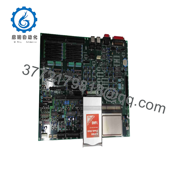
KOMS-A2 CXP-544A
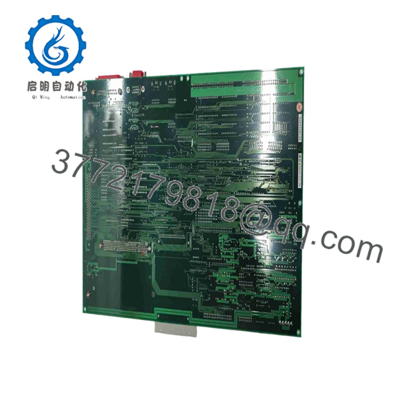
KOMS-A2 CXP-544A
Technical Notes & Best Practices
- Hardware Jumper Configuration: Always clone jumper block settings (address selection, baud rates, bus termination) from the old CXP-544A board prior to installation. Incorrect jumper layouts can cause system boot halts or bus conflicts.
- Onboard Battery Check: If the motherboard utilizes a real-time clock (RTC) battery or CMOS retention cell, test its voltage (typically ~3.0V DC) before installation to ensure non-volatile parameters are retained during power loss.
- ESD Safe Handling: Due to high-density CMOS logic chips on the PCBA, store and transport uninstalled units in anti-static shielding bags.
Frequently Asked Questions (FAQ)
What equipment uses the KOKUSAI KOMS-A2 / CXP-544A board?
It is primarily installed in KOKUSAI industrial automation systems, including semiconductor processing tools and specialized thermal equipment requiring dedicated real-time control logic.
Is the interchangeable with other KOKUSAI motherboard revisions?
The KOMS-A2 marking explicitly designates the revision layout. To maintain pin-for-pin and bus timing compatibility, replace failing boards with an identical KOMS-A2 unit unless factory engineering documentation approves a higher revision level.
What should I check if the replacement board does not boot?
First verify that all DC power supply voltages (+5V, +12V) are within specification at the board input header. Next, check that memory modules are firmly seated and that hardware address DIP switches match your system’s original board configuration.



