
 WhatsApp: +86 16626708626
 Email:
  Phone: +86 16626708626
Description
3. Key Technical Specifications
| Parameter | Value |
|---|---|
| Bus Standard | VMEbus (IEEE 1014-1987) |
| Architecture | 32-bit VME system |
| Processor Type | Motorola 68k / PowerPC (variant-dependent) |
| Memory | Onboard RAM + EPROM/Flash |
| Power Supply | +5 V, ±12 V (VME backplane) |
| I/O Interfaces | Serial (RS-232), digital I/O (varies) |
| Form Factor | 6U VME card (typical) |
| Connector | 96-pin DIN VME connector |
| Operating Temp | 0 to +60°C (industrial grade) |
| Storage Temp | −40 to +85°C |
| MTBF | >100,000 hours (typical VME class) |
| Weight | ~0.45 kg |
4. Product Introduction
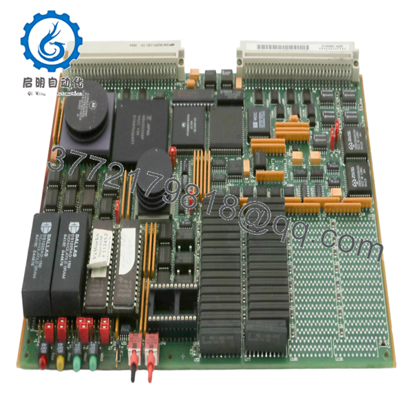
The Motorola 01-W3781B03C is a VMEbus-based embedded controller module used in industrial control systems, defense electronics, and legacy automation platforms. It operates as either a CPU board or system interface within a VME rack, handling real-time data processing and communication across multiple modules.
In field systems, these boards are typically found in older DCS, test benches, or aerospace control racks where deterministic timing and hardware-level reliability matter more than modern computing power. Replacement demand is driven almost entirely by maintaining legacy systems rather than new installations.

- 01-W3781B03C
5. Installation & Configuration Guide
Stage 1: Pre-Installation Preparation (15–20 minutes)
- ⚠️ Safety First: Shut down the VME chassis, isolate power, lock out/tag out. Wait 5–10 minutes for bus discharge.
- Tools Required: ESD strap, flat screwdriver, multimeter, labeling tags, smartphone.
- Data Backup:
- Document slot position in VME rack
- Record jumper/DIP configurations (addressing, interrupts)
- Photograph all front-panel connections
Stage 2: Removing the Old Module (10 minutes)
- Loosen front panel retaining screws.
- Label all connected cables (serial, I/O).
- Use extraction levers to disengage from backplane.
- Pull straight out — do not tilt, or you’ll damage DIN connectors.
- Inspect backplane connectors for bent pins or oxidation.
- ⚠️ Note: Keep the old board for jumper reference.
Stage 3: Installing the New Module (10–15 minutes)
- Verify exact part number (01-W3781B03C) — suffix mismatch can break compatibility.
- Clone jumper/DIP settings exactly from old board.
- Align card with guide rails and insert evenly.
- Press firmly until fully seated in backplane.
- Tighten front panel screws to secure against vibration.
- Self-Checklist:
- Jumpers match
- Board fully seated
- Connectors aligned
- No bent pins
Stage 4: Power-On & Testing (15–25 minutes)
- Pre-Power Check: Verify no short on +5 V rail.
Power-On Steps:
- Power up VME chassis only.
- Observe board LEDs (CPU activity, bus status).
- Connect terminal via serial port (if applicable).
- Verify boot sequence or OS response.
- Check communication with other VME modules.
- ⚠️ Troubleshooting Note:
- No boot → check EPROM or CPU compatibility
- Bus error → address conflict or jumper misconfig
- Intermittent faults → suspect backplane connector wear
6. Frequently Asked Questions (FAQ)
Q1: Can I hot-swap this VME module?
No. Standard VME systems are not hot-swappable unless specifically designed for it. Pulling a live board can crash the entire rack or damage the backplane.
Q2: Is this model obsolete?
Yes. This is legacy Motorola VME hardware. Most available units are used or refurbished. New stock is extremely rare.
Q3: What replaces this module in modern systems?
There is no direct drop-in replacement. Migration typically involves:
- VME-to-CompactPCI or VPX transition
- Or full PLC/DCS redesign
If uptime matters, most plants keep spare boards instead of migrating immediately.
Q4: Will removing this board affect system logic?
Yes—this may be a CPU or system controller. Removing it can stop the entire system.
Always confirm its role before pulling it.
Q5: Why are these boards still expensive despite being old?
Because they’re tied to critical legacy systems. Downtime costs far more than the hardware.
Q6: What’s the most common failure mode?
Aging components—EPROM failure, capacitor degradation, and connector wear.
I’ve seen boards pass power tests but fail under load due to bus timing issues.
Q7: Can I repair this board easily?
Not realistically. These are multilayer PCBs with proprietary firmware.
Board-level repair is possible but rarely cost-effective compared to replacement.
Quality Control & Testing SOP (Transparency)
1. Inbound Inspection & Traceability
- Verified part number and revision: 01-W3781B03C
- Serial number recorded
- Visual inspection: no PCB burns, no trace repair, no corrosion
- Edge connectors inspected for wear
2. Live Functional Testing
- Tested in a genuine VME chassis test rack
- Power-on and CPU initialization verified
- Serial communication test performed
- Bus communication with companion modules validated
- 24-hour runtime stability test
- Test report generated
3. Electrical Parameter Testing
- Insulation resistance >10 MΩ @ 500 V
- Power rail verification (+5 V, ±12 V)
- Ground continuity check
4. Firmware & Configuration Verification
- EPROM presence and labeling verified
- Jumper/DIP configuration documented
5. Final QC & Packaging
- Anti-static ESD bag
- Foam-protected industrial packaging
- QC Passed label with traceable ID
Test photos and functional videos available upon request.
Technical Pitfalls & Survival Guide
❗ Firmware / EPROM Dependency
These boards often rely on specific firmware versions.
I’ve seen replacements boot to nothing because the EPROM didn’t match the system.
❗ Jumper Configuration Errors
VME addressing is not forgiving.
Wrong jumper → bus conflict → system crash.
Take a photo before removal. Always.
❗ Backplane Connector Damage
If you angle the board during insertion, you’ll bend DIN pins.
Now you’ve got intermittent faults that are painful to diagnose.
❗ Power Load Assumptions
Older VME racks run close to PSU limits.
Adding a slightly different board revision can push the supply over the edge.
❗ ESD Handling
These boards are not modern ESD-hardened designs.
I’ve watched one die instantly after improper handling.


