
 WhatsApp: +86 16626708626
 Email:
  Phone: +86 16626708626
Description
3. Key Technical Specifications
| Parameter | Value |
|---|---|
| Architecture | 32-bit embedded processor |
| Bus Interface | VMEbus or proprietary embedded backplane |
| CPU Type | Motorola 68k / PowerPC class (variant dependent) |
| Memory | Onboard DRAM + Flash/EPROM |
| I/O Interfaces | Serial (RS-232/422), optional digital I/O |
| Form Factor | Rack-mounted CPU board/module |
| Power Supply | +5 V, ±12 V (backplane supplied) |
| Operating Temperature | 0 to +60°C |
| Storage Temperature | −40 to +85°C |
| System Role | Main controller or subsystem CPU |
| Indicators | RUN / ERR / BUS activity LEDs |
| Weight | ~0.5–1.5 kg |
Field Note: “CPX2000” is a platform designation used across multiple configurations. Exact CPU type, memory size, and I/O vary by revision. Always verify the specific board ID or subassembly number.
4. Product Introduction
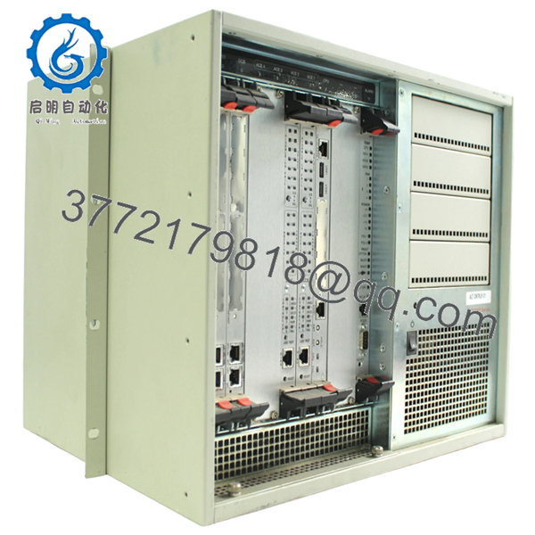
The Motorola CPX2000 is an embedded CPU controller module used in legacy industrial automation, telecommunications, and test systems. It typically operates within a rack-based architecture (often VMEbus or similar), executing control logic, communications, and coordination between I/O modules.
In field systems, CPX2000 units are often found as the central processor in older DCS nodes or specialized equipment. Replacement demand is driven by lifecycle constraints—plants keep these systems running for decades, and a failed CPU can stop the entire process.

- CPX2000
5. Installation & Configuration Guide
Stage 1: Pre-Installation Preparation (15–20 minutes)
- ⚠️ Safety First: Shut down system, isolate power, lock out/tag out. Wait 5–10 minutes for discharge.
- Tools Required: ESD strap, screwdriver, multimeter, labels, smartphone.
- Data Backup:
- Document slot location and system role
- Record DIP/jumper settings
- Capture serial console configuration and boot logs
Stage 2: Removing the Old Module (10 minutes)
- Remove front panel screws or retaining clips.
- Label all connected cables.
- Use ejector levers (if present) to release board.
- Pull straight out — avoid twisting.
- Inspect backplane connectors for wear or bent pins.
- ⚠️ Note: Keep the old module for configuration reference.
Stage 3: Installing the New Module (10–15 minutes)
- Verify exact model and revision — CPX2000 variants are not interchangeable.
- Clone all jumper/DIP settings precisely.
- Insert along guide rails evenly.
- Seat firmly into backplane connectors.
- Secure front panel hardware.
- Self-Checklist:
- Jumpers match
- Fully seated
- Connectors aligned
- Cabling restored
Stage 4: Power-On & Testing (20–30 minutes)
- Pre-Power Check: Verify +5 V rail stability.
Power-On Steps:
- Power up rack/system.
- Observe CPU LEDs (RUN/ERR).
- Connect via serial console.
- Verify boot sequence and firmware load.
- Check communication with I/O modules.
- ⚠️ Troubleshooting Note:
- No boot → firmware/EPROM mismatch
- Bus fault → addressing conflict or jumper error
- Intermittent resets → power supply instability
6. Frequently Asked Questions (FAQ)
Q1: Can this CPU be hot-swapped?
No. Standard VME/embedded systems using CPX2000 are not hot-swappable. Removing it under power risks system crash and hardware damage.
Q2: Is CPX2000 still manufactured?
No. This is legacy hardware. Available units are typically refurbished or surplus.
Q3: Is there a direct modern replacement?
Not as a drop-in. Migration usually requires:
- Replacing the entire control rack
- Rewriting software for a PLC/DCS platform
Most facilities keep spare CPUs instead.
Q4: Will replacing the CPU erase my program?
Programs are usually stored externally or in non-volatile memory, but firmware compatibility is critical. Mismatch can prevent boot.
Q5: Why is identifying the exact variant important?
Because CPX2000 is a platform name, not a single hardware configuration. CPU type, memory, and I/O vary across revisions.
Q6: What are typical failure modes?
- Aging capacitors
- EPROM corruption
- Connector oxidation
I’ve seen boards pass power tests but fail under bus load.
Q7: Why are tested units priced higher?
Because verification requires a compatible rack and firmware environment. Untested units are a risk in production systems.
Quality Control & Testing SOP (Transparency)
1. Inbound Inspection & Traceability
- Verified model and revision markings
- Serial number recorded
- PCB inspection: no burn marks, no rework traces
- Connector edges inspected under magnification
2. Live Functional Testing
- Tested in compatible VME/embedded rack
- Power-on and boot sequence verified
- Serial console communication confirmed
- I/O module communication validated
- 24-hour continuous runtime test
- Thermal monitoring using Fluke IR thermometer
3. Electrical Parameter Testing
- Insulation resistance >10 MΩ @ 500 V
- Power rail verification (+5 V, ±12 V)
- Ground continuity confirmed
4. Firmware & Configuration Verification
- EPROM presence and labeling documented
- Jumper/DIP configuration recorded
5. Final QC & Packaging
- Anti-static ESD packaging
- Foam-protected shipping carton
- QC Passed label with inspection date
Test reports and boot verification videos available upon request.
Technical Pitfalls & Survival Guide
❗ Variant Confusion
“CPX2000” alone is not enough.
I’ve seen engineers install the wrong revision—system powered up but never booted. Always confirm subassembly numbers.
❗ Firmware Dependency
Without matching firmware, the board may not initialize.
EPROM differences can stop the system cold.
❗ Jumper/DIP Misconfiguration
Addressing errors cause bus conflicts.
Take photos before removal—don’t rely on memory.
❗ Backplane Wear
Older racks develop intermittent contact issues.
If faults persist, don’t assume the CPU is bad—check the backplane.
❗ Power Supply Margins
Legacy systems often run near PSU limits.
A slightly different board revision can introduce instability.
❗ ESD Handling
No modern protection.
I’ve seen boards fail before installation due to static discharge.


