
 WhatsApp: +86 16626708626
 Email:
  Phone: +86 16626708626
Description
3. Key Technical Specifications
| Parameter | Value |
|---|---|
| Bus Standard | VMEbus (IEEE 1014) |
| CPU Type | Motorola 68000 |
| Clock Speed | ~8 MHz |
| Data Width | 16/32-bit architecture |
| Memory | Onboard DRAM + EPROM |
| I/O Interfaces | Serial (RS-232), optional parallel I/O |
| Form Factor | 6U VME card |
| Connector | 96-pin DIN VME backplane |
| Power Supply | +5 V, ±12 V via VME rack |
| Operating Temp | 0 to +55°C |
| Storage Temp | −40 to +85°C |
| Weight | ~0.5 kg |
4. Product Introduction
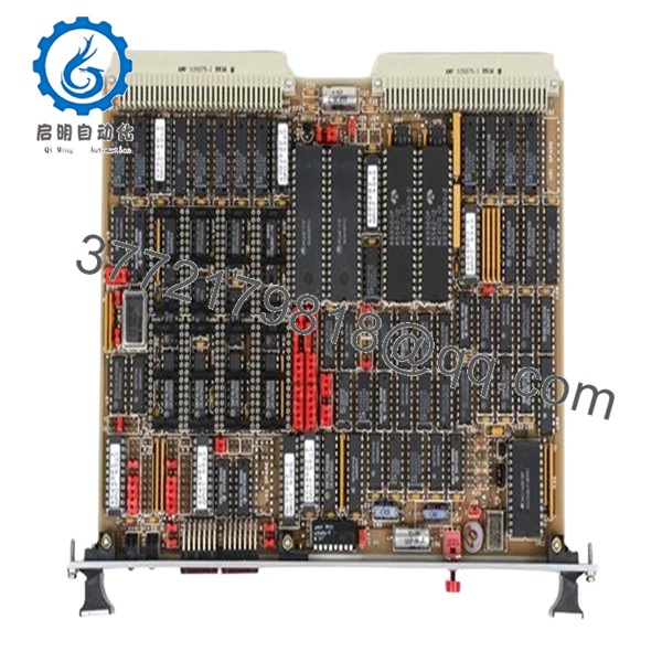
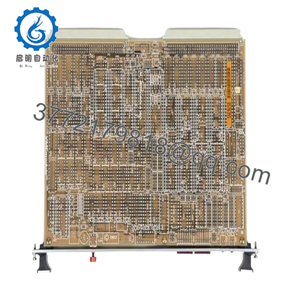
The Motorola MVME050 is an early-generation VMEbus single board computer based on the Motorola 68000 processor. It serves as a CPU module in legacy industrial control systems, test equipment, and defense electronics where deterministic timing and stable hardware interfaces are required.
In real installations, this board is typically found in older VME racks handling supervisory control or communication tasks. Replacement demand today is driven by lifecycle maintenance—these systems often remain in service because rewriting the application for a modern platform is not justified.
5. Installation & Configuration Guide
Stage 1: Pre-Installation Preparation (15–20 minutes)
- ⚠️ Safety First: Shut down VME rack, isolate power, lock out/tag out. Wait 5–10 minutes for discharge.
- Tools Required: ESD strap, flat screwdriver, multimeter, labels, smartphone.
- Data Backup:
- Record slot position and system role
- Document jumper/DIP settings (addressing, boot mode)
- Capture serial console parameters
Stage 2: Removing the Old Module (10 minutes)
- Loosen front panel retaining screws.
- Label all connected cables.
- Use ejector handles to disengage board.
- Pull straight out — avoid bending DIN connectors.
- Inspect backplane for dust, oxidation, or bent pins.
- ⚠️ Note: Keep the old board for configuration reference.
Stage 3: Installing the New Module (10–15 minutes)
- Verify exact model (MVME050) — similar MVME models are not interchangeable.
- Clone jumper/DIP settings exactly.
- Insert board along guide rails.
- Seat firmly into backplane connectors.
- Secure front panel screws.
- Self-Checklist:
- Jumpers match
- Fully seated
- Connectors aligned
- Cabling restored
Stage 4: Power-On & Testing (20–30 minutes)
- Pre-Power Check: Confirm +5 V rail stability.
Power-On Steps:
- Power up VME rack.
- Observe LEDs (RUN/ERR indicators).
- Connect via serial terminal.
- Verify boot sequence (monitor/firmware prompt).
- Confirm communication with other VME modules.
- ⚠️ Troubleshooting Note:
- No boot → EPROM issue or incorrect jumper settings
- Bus error → addressing conflict
- Intermittent faults → backplane connector wear

- MVME050
- MVME050
6. Frequently Asked Questions (FAQ)
Q1: Can I hot-swap the MVME050?
No. Standard VME systems do not support hot swapping. Removing the board under power risks backplane damage and system failure.
Q2: Is this board still manufactured?
No. This is legacy hardware from early VME deployments. Availability is limited to refurbished or surplus units.
Q3: Is there a direct modern replacement?
No direct drop-in replacement exists. Migration typically requires redesign to CompactPCI, VPX, or PLC/DCS platforms.
Q4: Will replacing the CPU erase my system software?
Not necessarily. Software is often stored in EPROM or external storage. However, firmware compatibility must match exactly.
Q5: What are common failure modes?
- EPROM degradation
- Capacitor aging
- Connector wear
I’ve seen boards fail intermittently due to marginal contact on the backplane.
Q6: Why are these boards still in use?
Because the systems they support are stable and validated. Replacing the entire platform introduces risk and cost.
Q7: How do I verify compatibility before purchase?
Check:
- Exact model number (MVME050 vs similar variants)
- Firmware/EPROM version
- Jumper configuration
Quality Control & Testing SOP (Transparency)
1. Inbound Inspection & Traceability
- Verified model: MVME050
- Serial number recorded
- PCB inspection: no burns, no rework marks
- Edge connectors inspected for wear
2. Live Functional Testing
- Tested in VME chassis with compatible modules
- Power-on and boot sequence verified
- Serial communication test completed
- Inter-module communication validated
- 24-hour continuous runtime test
- Thermal monitoring using Fluke IR thermometer
3. Electrical Parameter Testing
- Insulation resistance >10 MΩ @ 500 V
- Power rail verification (+5 V, ±12 V)
- Ground continuity confirmed
4. Firmware & Configuration Verification
- EPROM presence and labeling documented
- Jumper/DIP configuration recorded
5. Final QC & Packaging
- Anti-static ESD packaging
- Foam-protected shipping carton
- QC Passed label with inspection date
Test reports and boot verification videos available upon request.
Technical Pitfalls & Survival Guide
❗ EPROM / Firmware Mismatch
This board depends heavily on firmware.
I’ve seen replacements sit dead because EPROM versions didn’t match the system.
❗ Jumper Configuration Errors
Addressing and boot settings are manual.
Wrong jumper → system won’t boot or conflicts on the bus.
❗ Backplane Connector Wear
Older VME racks develop intermittent contact issues.
Don’t assume the board is faulty until you check the backplane.
❗ Power Supply Margins
Legacy racks often run near PSU limits.
A marginal supply can cause random resets.
❗ ESD Handling Damage
No modern protection.
Improper handling can destroy the board before installation.


