
 WhatsApp: +86 16626708626
 Email:
  Phone: +86 16626708626
Description
3. Key Technical Specifications
⚠️ Important: Public datasheets for NTFX75BA are extremely limited. This part typically appears in telecom switching or embedded control racks. Verify against your system BOM before procurement.
- Module Type: Telecom control / interface board
- System Integration: Rack-based modular systems (carrier-grade platforms)
- Bus Interface: Proprietary backplane (not standard VME)
- Function Role: Signal routing / control logic / interface handling
- Form Factor: Slot-based plug-in module
- Power Supply: Backplane powered (typically −48 V telecom or +5 V logic rails depending on chassis)
- Operating Environment: Telecom-grade (0 to +50 °C typical, extended variants possible)
- Connector Type: High-density backplane connector
- Application Areas: Telecom switching systems, base station control, legacy network infrastructure
- Lifecycle Status: Obsolete, aftermarket supply only
4. Product Introduction
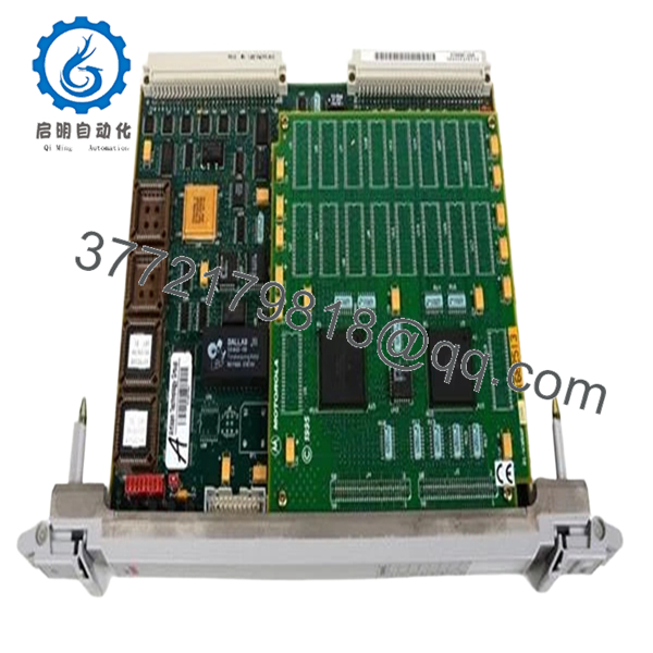
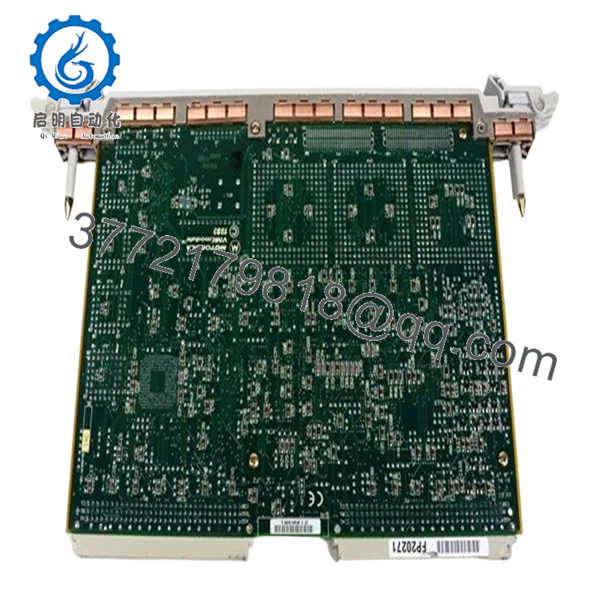
The Motorola NTFX75BA is a telecom-grade control/interface module used in legacy carrier systems, typically installed in rack-based switching or base station infrastructure. It handles internal system communication, signal routing, or subsystem coordination depending on the host platform.
In real deployments, this type of board is not used standalone—it is tightly coupled to a specific chassis and firmware environment. Engineers usually source it for maintenance of long-running telecom systems where replacing the entire platform is not economically viable.
5. Installation & Configuration Guide
Stage 1: Pre-Installation Preparation (10–15 minutes)
- ⚠️ Safety First:
- Notify operations (telecom systems often run 24/7)
- Follow lockout/tagout for DC supply (commonly −48 V systems)
- Wait for full discharge
- Tools Required:
- ESD wrist strap
- Insulated screwdriver
- Multimeter (Fluke 115 recommended)
- Labels and smartphone
- Data Backup:
- Document slot position and system role
- Record system alarms or active faults
- Photograph module orientation and adjacent cards
Stage 2: Removing the Old Module (5–10 minutes)
- Identify correct slot (telecom racks are dense—double-check)
- Label all associated cables or front-panel connectors
- Release locking levers
- Pull module straight out
- ⚠️ Note:
Telecom backplanes are high-density. If you angle the board, you will bend pins. I’ve seen entire shelves go offline from one bad pull.
Stage 3: Installing the New Module (10 minutes)
- ESD grounding required
- Verify exact part number: NTFX75BA (suffix matters)
- Configuration Check (Critical):
- Confirm jumper or DIP settings (if present)
- Ensure compatibility with system firmware release
- Insert along guide rails
- Apply even pressure until fully seated
- Lock retaining mechanism
- Checklist:
- Correct slot position
- Fully seated
- Lock engaged
Stage 4: Power-On & Testing (15–30 minutes)
- Pre-check:
- Verify supply voltage stability (−48 V or logic rails depending on system)
- Power-On Steps:
- Restore system power
- Monitor system controller alarms
- Check module status LEDs
- Verify communication with system controller
- Run system diagnostics (if available)
- ⚠️ Troubleshooting Note:
- No recognition → firmware incompatibility
- Alarm persists → wrong slot assignment or provisioning issue
- Intermittent faults → backplane connector wear

- NTFX75BA
- NTFX75BA
6. Frequently Asked Questions (FAQ)
Q1: What exactly does the NTFX75BA do?
Honestly, it depends on the system. These telecom modules are highly application-specific. Without the original system manual, you won’t know its exact role—control, signaling, or interface.
Q2: Can I use this in a standard VME or PLC system?
No. This is not a general-purpose module. It’s designed for a specific telecom chassis with proprietary backplane signaling.
Q3: Is this model still manufactured?
No. It’s obsolete. Availability is limited to surplus inventory and secondary market sources.
Q4: What’s the biggest risk when replacing this module?
❗ Firmware mismatch or system provisioning issues.
I’ve seen perfectly good hardware rejected by the system because the firmware revision didn’t match the controller database.
Q5: Why is there almost no documentation available?
These boards were deployed in carrier-grade systems with restricted documentation. Most details stayed within OEM service manuals, not public datasheets.
Q6: How do I verify compatibility before buying?
- Check system BOM or spare parts list
- Match full part number including suffix
- Confirm firmware/software release compatibility
Q7: Any field advice before installation?
- ❗ Never assume slot interchangeability
- ❗ Always log system alarms before removal
- ❗ Keep the old module until the system is stable


