
 WhatsApp: +86 16626708626
 Email:
 Phone: +86 16626708626
Description
Core Product Summary
The Bosch Rexroth Indramat TVD 1.3-15-03 (material number R911268888) is a power supply module from the TVD 1.3 family, designed for direct connection to 3 x AC 380…480 V, 50…60 Hz three-phase mains without a transformer. It rectifies the mains input into a regulated 320 V DC bus that feeds the connected Indramat drive modules, supplies the +24VL and ±15VM signal voltages to the drive electronics, and absorbs regenerated braking energy in an internal bleeder resistor — the TVD 1.3 operates without mains regeneration.
The 15 kW version provides 15 kW continuous DC bus power with short-duration overload capability for accelerating feed and spindle drives, and can power up to ten drive modules, supporting drive packages with a continuous mechanical output of up to 12 kW. Integration uses a modular architecture: an internal power contactor disconnects the drives from the mains, DC bus dynamic braking can be applied on E-stop, and auxiliary components — the NAM 1.3 power adapting module (which integrates the commutation choke, DC bus smoothing choke, and mains connection), or individual components such as the GLD 17 smoothing choke, buffer capacitors, and the TBM 1.2 additional bleeder module — are matched to the 15 kW rating. Extensive monitoring functions with front-panel diagnostic LEDs, a ready-state contact, and a Power OK contact shut off drive power immediately if a fault occurs.
Key Technical Specifications
| Parameter | Value |
|---|---|
| Product type | Power supply module for the modular Indramat AC drive system |
| Series | TVD 1.3 (15 kW version, designation TVD 1.3-15-03) |
| Mains input | 3 x AC 380…480 V ±10%, 50…60 Hz, direct connection without transformer |
| DC bus voltage | 320 V ±5%, regulated |
| Continuous DC bus power | 15 kW |
| Peak DC bus power | 45 kW for 0.3 s (short-duration overload for acceleration) |
| Regeneration behavior | No mains regeneration; regenerated power is absorbed by the bleeder resistor and converted into heat |
| Internal bleeder resistor power | 440 W (TVD 1.3-15) |
| Drive support | Up to 10 drive modules; drive packages up to 12 kW continuous mechanical output |
| Signal voltages | ‘+24VL (22…26 V) and ±15VM supplied to all connected drive modules; -15VM max. 2 A, +15VM and -15VM combined max. 4 A; in a power failure the signal voltages are supplied from the DC bus circuit |
| Power contactor | Internal power contactor disconnects the drives from the mains |
| DC bus dynamic braking | Optional, applied for controlled stopping of drives on E-stop or power failure |
| Monitoring functions | Mains voltage, DC bus voltage, overcurrent, braking (bleeder) power, heatsink temperature, overvoltage fuse, signal voltages |
| Diagnostic displays | Green LEDs: +24V/±15V, Bb1 (ready), MAINS, POWER; red LEDs: I-FAULT, P-FAULT, T-FAULT, U-FAULT; RESET key on the front |
| Status contacts | Ready-state contact (Bb1); Power OK output UD, potential-free, max. DC 24 V/1 A or AC 250 V/1 A; mains contactor and temperature pre-warning contacts |
| Ambient temperature (rated values) | ‘+5 to +45 °C; maximum permissible +55 °C (with derating) |
| Storage/transport temperature | −30 to +85 °C |
| Installation elevation | Max. 1000 m above sea level (power data derates above) |
| Relative humidity | Max. 95% |
| Protection category | IP 10 per DIN 40 050 |
| Contamination | Non-conductive dirt, no condensate |
| Weight (TVD 1.3 family) | 10.5 kg or 11.2 kg depending on module power rating |
Detailed Product Overview
In the Indramat modular AC drive system, the TVD 1.3-15-03 is the central power block. One mains connection feeds the supply module, which rectifies the three-phase input and holds the DC bus at a regulated 320 V for all downstream drive modules (such as the TDM, TDA, KDA, and DDS drive controllers), connected through busbars and a shared DC bus circuit. Because the bus is regulated, drive dynamics are maintained even during mains undervoltage, and the drive electronics stay functional through short power interruptions because their signal voltages are drawn from the DC bus.
The 15 kW continuous rating is the key sizing figure: drive packages with a continuous mechanical output up to 12 kW can be run from the TVD 1.3 line, and the module supplies up to ten drive modules. The 45 kW peak DC bus capability (0.3 s) covers the short overloads that occur when feed and spindle drives accelerate, so the supply does not need to be oversized for peak loads. When the drives operate in generator mode during braking, the regenerated power cannot be returned to the line — the TVD 1.3 operates without mains regeneration — and the internal 440 W bleeder resistor converts it into heat. For applications with higher regenerated power, an additional TBM 1.2 bleeder module or an external bleeder resistor mounted outside the control cabinet can be connected; with an external bleeder, the internal bleeder becomes inoperative, which reduces heat dissipation inside the cabinet.
Electrical integration is defined by the module’s required periphery. The TVD 1.3-15-03 must always be operated with a DC bus smoothing choke in the L+ line — the GLD 17 for the 15 kW version, or the NAM 1.3-15 power adapting module, which bundles the commutation choke, smoothing choke, and mains connection devices into one unit and suppresses reactions on the power system. Lead cross-sections are specified by rating: at least 16 mm² for the mains leads and 6 mm² for the associated connections with the TVD 1.3-15, and at least 10 mm² for the DC bus connection (max. 1 m twisted). The electronics supply and signal exchange to the drive modules run through the 16-pin wire-ribbon cable at terminal X1, which must be completed with a terminating plug — the high-voltage section will not power up without it. Fusing can be implemented with power circuit-breakers or gL fuse links; semiconductor fuses are not required.
The monitoring concept is central to how these systems fail safely. The module continuously watches mains voltage, DC bus voltage, power-section current, bleeder load, and heatsink temperature. On any fault, the ready-state contact causes the power supplied to the drives to be shut off immediately, and — in configurations with DC bus dynamic braking — the drives are braked to a standstill. The front panel provides the four green status LEDs (+24V/±15V, Bb1, MAINS, POWER) and four red fault LEDs (I-FAULT for overcurrent, P-FAULT for excessive braking power, T-FAULT for over-temperature, U-FAULT for DC bus overvoltage), plus a RESET key; signal and unit locking is stored and cleared by the reset key or by re-switching the electronics supply. Potential-free contacts report Power OK (UD) and mains contactor status, and a temperature pre-warning can be used for example as a condition for releasing door interlocks.
Installation is control-cabinet work. The module and its drive modules are designed for installation in a control cabinet or closed housing meeting IP 10, arranged so that the drive requiring the greatest power and current is nearest to the supply, and observing the cabinet spacing dimensions given in the manual. The bleeder resistor remains hot after power-off, so flammable materials must be kept at least 300 mm above and 40 mm to the side and front of it. Voltages up to 700 V occur in the power section: all power must be locked out before work, de-energization verified by measurement, and approximately five minutes allowed for DC bus discharge.
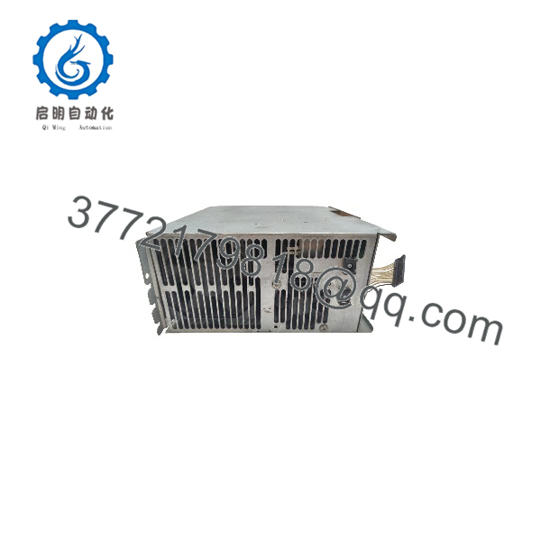
R911268888
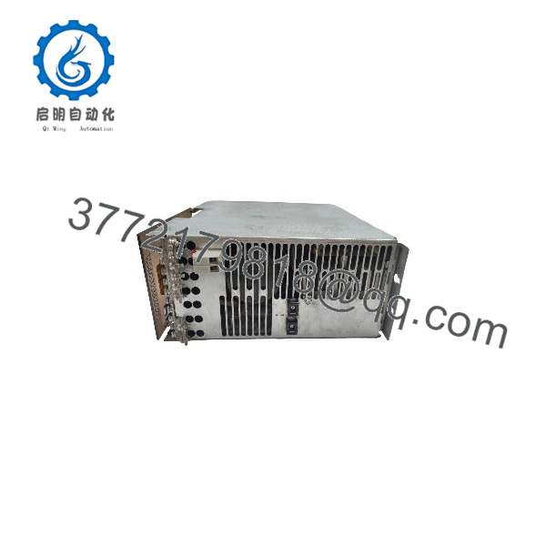
R911268888
System Compatibility & Integration Requirements
| Item / Dependency | Verified Compatibility or Requirement | Practical Note |
|---|---|---|
| Drive system | Modular Indramat AC drive system (e.g. TDM/TDA/KDA/DDS drive controllers); drives up to 12 kW continuous mechanical output | Up to 10 drive modules can be supplied from one TVD module |
| Mains supply | 3 x AC 380…480 V ±10%, 50…60 Hz | Direct connection without a transformer |
| Mains connection devices | Power circuit-breakers or gL fuse links; semiconductor fuses not required | Follow the recommended fusing for the mains supply conductors in the applications manual |
| Power adapting module | NAM 1.3-15 (contains commutation choke, DC bus smoothing choke, mains connection) | Alternative: individual components per the interconnection diagram |
| DC bus smoothing choke | Required in the L+ line at all times: GLD 17 for the TVD 1.3-15 (or the NAM 1.3-15) | The high-voltage section checks this connection at power-up |
| Lead cross-sections (TVD 1.3-15) | Mains leads min. 16 mm²; associated connections min. 6 mm²; DC bus min. 10 mm² (max. 1 m twisted) | Per EN 60204, installation type B1 |
| Additional bleeder | TBM 1.2 additional bleeder module, or an external bleeder resistor | External bleeder is installed outside the cabinet (e.g. rear panel); the internal bleeder then becomes inoperative |
| Additional DC bus capacitance | Buffer/auxiliary capacitance modules (CZ, TCM 1.1 types) per the order information | Electronics supply buffer capacitor: max. 680 µF, rated for the EPU voltage (up to 450 V DC) |
| Drive electronics supply | 16-pin wire-ribbon cable at X1; +24VL and ±15VM | Connection must be completed with the terminating plug; the high-voltage section will not power up without it |
| Control signals | Plug-in terminals on the front for control inputs, status messages, and 24 V / ±15 V outputs; signal voltages accessible at X3 for test purposes | If used outside the TVD, keep connections short and use shielded leads to avoid coupling interference |
| Blower supply | Mains connector for blower supply must be ordered separately (socket order number 219 118) | Per the electrical connecting accessories overview |
| E-stop concept | Interconnect with DC bus dynamic braking, with E-stop relay, without dynamic braking, or for position-controlled braking — chosen by the machine builder | The DC bus dynamic brake brings motors to a standstill in fault and E-stop situations |
| Installation | Control cabinet or closed housing, IP 10 per DIN 40 050 | Place the highest-power drive nearest to the supply; observe spacing dimensions and safety clearances |
Dimensions, Mounting & Connection Notes
| Item | Verified Value |
|---|---|
| Mounting | Control cabinet or closed housing (IP 10 per DIN 40 050); cabinet installation requirements per the applications manual |
| Mounting hardware | M5 screws; tightening torque MA = 3 Nm; shock protection min. 80 mm below the module |
| Front panel elements | Diagnostic LEDs (+24V/±15V, Bb1, MAINS, POWER green; I-FAULT, P-FAULT, T-FAULT, U-FAULT red), RESET key, plug-in terminals for control inputs, status messages, and 24 V / ±15 V outputs, rating plate |
| Safety clearances | Bleeder resistor: keep flammable materials at least 300 mm above and 40 mm to the side and front |
| Ambient temperature | ‘+5 to +45 °C rated; max. +55 °C permissible with derating |
| Storage/transport temperature | −30 to +85 °C |
| Installation elevation | Max. 1000 m above sea level |
| Humidity / contamination | Max. 95% relative humidity; non-conductive dirt, no condensate |
| Weight (family) | 10.5 kg or 11.2 kg depending on module power rating |
Connection notes: the interconnection diagram in the manufacturer documentation is a recommendation; the wiring diagram of the machine builder governs the actual installation. Mains connection is made at the power-circuit terminals (1U1/1V1/1W1, 2U1/2V1/2W1); the periodic overvoltage between any phase and the housing may not exceed 1000 V peak, and permissible non-periodic overvoltages per VDE 0160 are defined in the manual. Before a high-voltage test of the control cabinet, all connections to the supply module must be disconnected. The DC bus smoothing choke connection between X7/1L+ and X7/2L+ must be present, or the power section will not enable. Dangerous voltages up to 700 V occur at the connections to the supply, chokes, and capacitors: lock out power before any work, verify de-energization by measurement, and allow approximately five minutes for DC bus discharge.
FAQ
What is the Bosch Rexroth TVD 1.3-15-03?
It is a power supply module (material number R911268888) of the Indramat TVD 1.3 family for direct connection to 3 x AC 380…480 V mains, which rectifies the mains into a regulated 320 V DC bus, supplies the drive electronics’ signal voltages, and feeds up to ten connected drive modules.
How much power can it deliver?
The TVD 1.3-15-03 provides 15 kW continuous DC bus power with 45 kW peak DC bus power for 0.3 seconds, and can run drive packages with a continuous mechanical output of up to 12 kW.
Does the module regenerate braking energy back to the mains?
No, the TVD 1.3 operates without mains regeneration; regenerated power from braking drives is absorbed by the internal bleeder resistor (440 W on the 15 kW version) and converted into heat. An additional TBM 1.2 bleeder module or an external bleeder resistor can be connected for higher regenerated power.
Which auxiliary components does the 15 kW version require?
It must always be operated with a DC bus smoothing choke in the L+ line — the GLD 17, or the NAM 1.3-15 power adapting module, which combines the commutation choke, smoothing choke, and mains connection devices. Buffer capacitance modules and an additional or external bleeder module can be added per the application requirements.
How are the drive modules connected?
The drive modules connect to the DC bus via the busbars in the connecting accessories kit, and their electronics are supplied through the 16-pin wire-ribbon cable at terminal X1, which must be completed with a terminating plug — the high-voltage section will not power up without it.
What do the front-panel LEDs indicate?
Four green LEDs show signal voltages (+24V/±15V), the ready state of the module and drives (Bb1), the mains supply (MAINS), and the DC bus (POWER); four red LEDs indicate faults — I-FAULT (overcurrent in the power section), P-FAULT (excessive braking power), T-FAULT (heatsink over-temperature), and U-FAULT (DC bus overvoltage). Stored faults are cleared with the RESET key.
What happens if a fault occurs?
The ready-state contact on the TVD causes the power supplied to the drives to be shut off immediately; in configurations with DC bus dynamic braking, the drives are braked to a standstill. The Power OK contact (UD, max. DC 24 V/1 A or AC 250 V/1 A) signals proper operation of the power system to higher-level controls.
What installation environment does the module require?
It must be installed in a control cabinet or closed housing meeting IP 10 per DIN 40 050, at an ambient temperature of +5 to +45 °C (max. +55 °C with derating), up to 1000 m elevation, with non-conductive contamination and no condensate. The drive requiring the greatest power should be mounted nearest to the supply, and flammable materials must be kept at least 300 mm above and 40 mm beside and in front of the bleeder resistor.



