
 WhatsApp: +86 16626708626
 Email:
  Phone: +86 16626708626
Description
3. Key Technical Specifications
- Function Type: LVDT (Linear Variable Differential Transformer) signal conditioning + control output
- Input Type: LVDT position feedback signals
- Output Type: Servo control signal (analog drive)
- Application: Position feedback control loops (valves, actuators, turbine control)
- Supply Voltage: Typically 24 V DC (system dependent)
- Signal Processing: Differential analog signal amplification and demodulation
- Communication: Internal backplane / proprietary interface
- Mounting: PCB module or rack-mounted card
- Operating Temperature: −20 to +60°C (industrial enclosure typical)
- PCB Assembly: Includes conditioning circuitry + control logic
- System Role: Closed-loop position control interface
Confirmed in secondary market listings as an LVDT conditioning module and servo drive assembly
4. Product Introduction
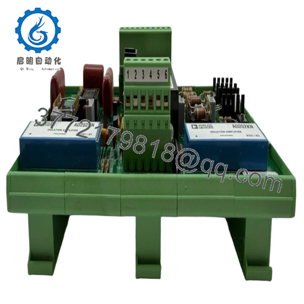
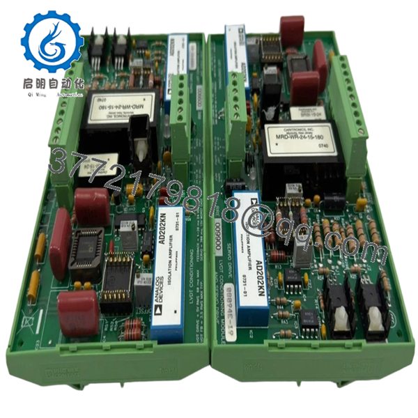
The Rolls-Royce RRE009900 (08094E-01) is an LVDT conditioning and control module used in closed-loop position control systems within turbine or marine automation platforms. It processes raw LVDT feedback signals and generates corresponding control outputs for actuators such as valves or pitch mechanisms.
In real installations, this module sits directly in the control loop—any instability or mismatch shows up immediately as position drift or oscillation. It is not a generic signal conditioner; calibration, scaling, and interface behavior are tightly coupled to the Rolls-Royce control architecture.

- RRE009900 08094E-01
- RRE009900 08094E-01
5. Installation & Configuration Guide
Stage 1: Pre-Installation Preparation (Estimated Time: 15 minutes)
- ⚠️ Safety First:
Isolate control system, apply lockout/tagout, confirm zero energy, wait 5 minutes. - Tools Required:
ESD strap, Fluke 115 multimeter, precision screwdriver, labeling tags, smartphone. - Data Backup:
- Record LVDT calibration parameters (zero/span)
- Capture controller tuning parameters (PID loop if applicable)
- Photograph wiring and shielding layout
Stage 2: Removing the Old Module (Estimated Time: 10 minutes)
- Identify module location in rack or enclosure.
- Label all LVDT and output wiring—these are easy to mix up.
- Disconnect wiring carefully (LVDT signals are low-level).
- Release mounting clips and extract module straight out.
- Inspect connectors for oxidation or looseness.
- ⚠️ Note: Keep the old module for reference during commissioning.
Stage 3: Installing the New Module (Estimated Time: 10–15 minutes)
- Wear ESD protection.
- Verify exact model: RRE009900 / 08094E-01 (no substitution).
- Insert module fully into slot—ensure firm seating.
- Reconnect wiring exactly as documented.
- Confirm shielding continuity (critical for LVDT signals).
Self-Checklist:
- LVDT inputs wired correctly (polarity matters)
- Output wiring verified
- Shield grounded at single point
- Module fully seated
Stage 4: Power-On & Testing (Estimated Time: 20 minutes)
- Pre-Power Check:
Verify stable 24 V DC supply and no short circuits.
Power-On Steps:
- Energize system without actuator load.
- Monitor module response (if diagnostic LEDs available).
- Check LVDT feedback signal stability.
- Perform manual position sweep test.
- Validate control loop response (no oscillation or lag).
- ⚠️ Troubleshooting Note:
- Oscillation → PID mismatch or signal noise
- No feedback → LVDT wiring or excitation failure
- Drift → grounding or shielding issue
6. Frequently Asked Questions (FAQ)
Q1: What exactly does this module do in the system?
It converts raw LVDT signals into usable position feedback and drives control outputs. Think of it as the “translator” between sensor physics and control logic.
Q2: Can I replace this with a generic LVDT signal conditioner?
No. You might replicate the signal, but not the system behavior. Rolls-Royce systems expect specific scaling and response characteristics.
Q3: What’s the most common failure mode?
Signal drift or noise. In my experience, 70% of “module failures” are actually grounding or shielding problems—not the board itself.
Q4: Is calibration required after replacement?
Yes, in most cases. Even identical modules can have slight offset differences. Always verify zero and span before returning to service.
Q5: Can this module be hot-swapped?
No. Pulling it live can inject noise into the control loop or damage the backplane. Shut down first.
Q6: Why is LVDT wiring so sensitive?
Because it’s a differential analog signal at low voltage levels. Poor shielding or routing introduces noise immediately into the control loop.
Q7: What’s the biggest mistake engineers make here?
❗ Ignoring polarity on LVDT inputs.
Reverse the wires, and your control loop goes unstable. I’ve seen valves slam shut because of this.


