
 WhatsApp: +86 16626708626
 Email:
  Phone: +86 16626708626
Description
3. Key Technical Specifications
| Parameter | Value |
|---|---|
| Function Role | Panel controller for marine automation |
| Processor | Embedded microprocessor (OEM-specific) |
| I/O Interfaces | Digital + analog I/O (DI/DO/AI/AO) |
| Application | Propulsion control, rudder/engine monitoring |
| Communication | Proprietary marine control network |
| Supply Voltage | Typically 24 V DC (marine standard) |
| Operating Temperature | −20 to +60°C |
| Humidity Rating | Up to 95% RH (non-condensing) |
| Environmental Design | Vibration + EMC tested for marine use |
| Mounting | Panel card / rack-mounted PCB |
| Condition in Market | Mostly used surplus units |
4. Product Introduction
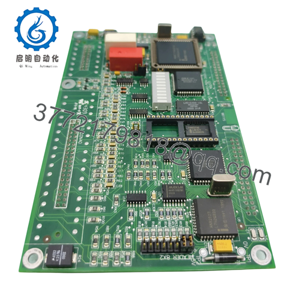
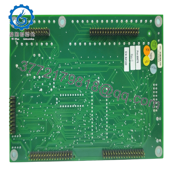
The Rolls-Royce Ulstein PCC1030C (961115) is a marine panel controller card used in propulsion and vessel automation systems. It handles real-time signal processing for inputs such as propeller speed, rudder angle, and system status, while issuing control outputs to actuators and interface panels.
In actual deployments, this card sits between operator panels and the control backbone. It is not a generic PLC module—its firmware, I/O mapping, and communication behavior are tightly bound to the Rolls-Royce / Kongsberg marine ecosystem. Most units in circulation today are pulled from vessels, so verification of revision and configuration is mandatory.

- PCC1030C 961115
- PCC1030C 961115
5. Installation & Configuration Guide
Stage 1: Pre-Installation Preparation (Estimated Time: 15 minutes)
- ⚠️ Safety First:
Notify bridge/engine control, isolate system, apply lockout/tagout, discharge power. - Tools Required:
ESD wrist strap, PH1 screwdriver, Fluke 115 multimeter, labeling tags, smartphone. - Data Backup:
- Record panel node assignment
- Capture I/O mapping and signal assignments
- Photograph connectors and wiring
- Document firmware/revision markings
Stage 2: Removing the Old Module (Estimated Time: 10 minutes)
- Open control cabinet or panel housing.
- Label all connectors (marine panels often reuse identical plugs).
- Disconnect wiring carefully—no force.
- Release retaining clips or screws.
- Pull module straight out to avoid backplane damage.
- ⚠️ Note: Keep the original board for troubleshooting reference.
Stage 3: Installing the New Module (Estimated Time: 10–15 minutes)
- Wear ESD protection.
- Verify exact model: PCC1030C / 961115 (no substitution).
- Insert module into slot—ensure full seating.
- Reconnect wiring exactly as documented.
- Secure all mechanical fasteners.
Self-Checklist:
- Model and revision match
- Connectors correctly assigned
- No bent pins
- Shield grounding intact
Stage 4: Power-On & Testing (Estimated Time: 20 minutes)
- Pre-Power Check:
Confirm stable 24 V DC and no short circuits.
Power-On Steps:
- Power up control rack (no propulsion load).
- Observe panel/system diagnostics.
- Verify controller card detection.
- Test input signals (rudder, RPM simulation if available).
- Confirm output commands respond correctly.
- ⚠️ Troubleshooting Note:
- No comms → Check backplane seating or node addressing
- Incorrect signals → Likely wiring mismatch
- Intermittent faults → Suspect connector oxidation (common in marine systems)
6. Frequently Asked Questions (FAQ)
Q1: Is this a standalone controller or part of a larger system?
Part of a larger system. It relies on the Rolls-Royce/Kongsberg marine control architecture. On its own, it won’t function.
Q2: Is this model still in production?
No. These are legacy modules. Most available units are salvaged or surplus from decommissioned vessels.
Q3: Can I replace it with a Siemens or ABB PLC module?
Not directly. You’d need a full system redesign—protocol conversion, logic rewrite, and HMI integration. This is not a drop-in replacement scenario.
Q4: What’s the most common failure mode?
Connector-related issues—corrosion, loose pins, or oxidized contacts. Electronics themselves are usually stable.
Q5: Will I lose configuration when swapping this board?
Core logic typically resides in the central control system, but I/O mapping and addressing must match exactly. Always document before removal.
Q6: What’s the biggest installation mistake?
❗ Misplacing connectors or assuming pin compatibility.
I’ve seen identical connectors swapped—result was reversed control signals on propulsion. Label everything before disconnecting.
Q7: Why is pricing inconsistent across suppliers?
Supply comes from dismantled vessels. Condition varies significantly—from clean pulls to heavily exposed boards. Always request test evidence.


