
 WhatsApp: +86 16626708626
 Email:
  Phone: +86 16626708626
Description
3. Key Technical Specifications
⚠️ Documentation Note: This board is not well documented publicly. Specs below are derived from VM-7 system architecture and field identification.
- System Compatibility: SHINKAWA VM-7 monitoring systems
- Board Type: Interface / signal conditioning PCB
- Function Role: Internal signal routing between sensor modules and controller
- Input Signals: Vibration / displacement probe signals (proximity probes typical)
- Output Handling: Processed signals to monitoring modules or recorder outputs
- PCB Type: Double-sided industrial PCB
- Mounting: Rack-mounted card (VM-7 chassis)
- Power Supply: Backplane powered (system dependent)
- Operating Environment: Industrial / turbine monitoring environments
- Application: Rotating equipment monitoring (turbines, compressors)
4. Product Introduction
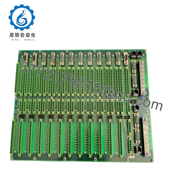
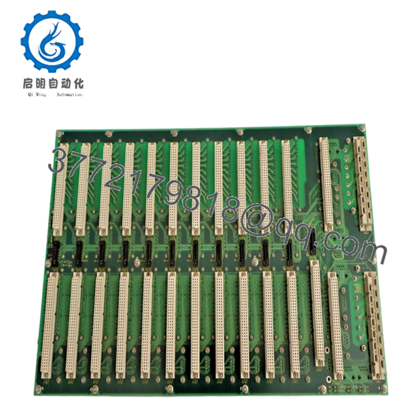
The SHINKAWA 2R10-021-P001B is an interface PCB used within VM-7 series vibration monitoring systems. It handles signal routing and conditioning between proximity probes, monitoring modules, and system outputs in rotating machinery protection systems.
In actual plant deployments—steam turbines, compressors, marine engines—this board sits behind the scenes. You don’t interact with it directly, but if it fails, you lose signal integrity across multiple channels. That’s why operators keep spares even after the system is considered obsolete.
5. Installation & Configuration Guide
Stage 1: Pre-Installation Preparation (10–15 minutes)
- ⚠️ Safety First:
- Notify operations (this is usually tied to critical machinery)
- Place machine in safe state or bypass protection if procedures allow
- Lock out/tag out system power
- Tools Required:
- ESD wrist strap
- PH1 screwdriver
- Fluke 115 multimeter
- Labels and smartphone
- Data Backup:
- Record channel assignments (probe → monitor mapping)
- Document alarm thresholds in controller
- Photograph board slot and cable connections
Stage 2: Removing the Old Module (5–10 minutes)
- Open VM-7 rack front panel
- Identify correct PCB slot (often multiple similar boards)
- Label any connectors or ribbon cables
- Remove retaining screws
- Pull board straight out
- ⚠️ Note:
These boards often sit in tight card cages. If you twist during removal, you risk damaging the backplane connector.
Stage 3: Installing the New Module (10 minutes)
- Apply ESD protection
- Verify exact part number: 2R10-021-P001B
- Configuration Clone (Critical):
- Match jumper settings (if present)
- Ensure correct slot position (some slots are function-specific)
- Insert along guide rails
- Seat firmly into backplane
- Secure screws
- Checklist:
- Correct slot
- Fully seated
- No loose connectors
Stage 4: Power-On & Testing (15–25 minutes)
- Pre-check: Verify system power rails
- Power-On Steps:
- Power system
- Observe VM-7 controller status
- Verify all channels show valid signal
- Inject test signal (if available)
- Confirm alarm and trip logic response
- ⚠️ Troubleshooting Note:
- Missing channels → incorrect slot or connector
- Noisy signal → grounding/shield issue
- No output → upstream probe or downstream module issue

- 2R10-021-P001B
- 2R10-021-P001B
6. Frequently Asked Questions (FAQ)
Q1: What exactly does this board do in the VM-7 system?
It acts as an internal signal distribution layer. It routes probe signals to monitoring modules and sometimes splits outputs to recorders. It’s not a standalone measurement module.
Q2: Is this interchangeable with other 2R10 series boards?
No. Even within the 2R10 family, function differs (e.g., vibration vs temperature modules). Always match the full part number.
Q3: Is this still available new?
Very unlikely. Most units on the market are used or refurbished, typically pulled from decommissioned systems.
Q4: What’s the most common failure mode?
Connector oxidation and signal drift. I’ve seen boards pass visual inspection but introduce noise into proximity probe signals, triggering false alarms.
Q5: Can I upgrade to a newer system instead of replacing this?
Yes, but that’s a full migration—usually to SHINKAWA VM-700 or other modern monitoring systems. That involves rewiring probes, reconfiguring logic, and downtime planning.
Q6: Why is signal integrity so critical here?
Because this board sits between sensors and protection logic. A bad signal doesn’t just give wrong data—it can trip a turbine or fail to trip when it should.
Q7: Any field advice before commissioning?
- ❗ Verify probe signal quality before and after replacement
- ❗ Check shielding continuity (this is where most noise comes from)
- ❗ Run a live vibration test before returning to service


