
 WhatsApp: +86 16626708626
 Email:
  Phone: +86 16626708626
Description
3. Key Technical Specifications
- Measurement Type: Axial displacement (thrust position)
- Input Signal: Eddy current proximity probe
- Measurement Range: ±2 mm typical (configurable variants exist)
- Accuracy: ±1% full scale
- Output Signals:
- 4–20 mA analog
- BNC dynamic signal output
- Relay alarm outputs
- Alarm Levels: 2 levels (Alert / Danger)
- Power Supply: 24 V DC ±10%
- Operating Temperature: 0 to +60 °C
- Mounting: Rack-mounted (VM-3 chassis)
- Application: Turbine, compressor, rotating machinery protection
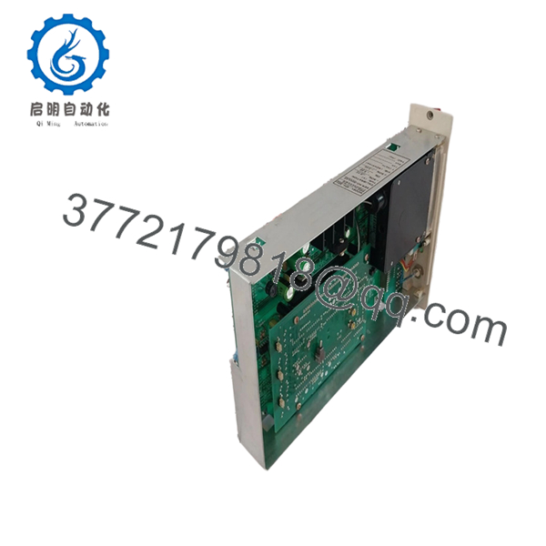
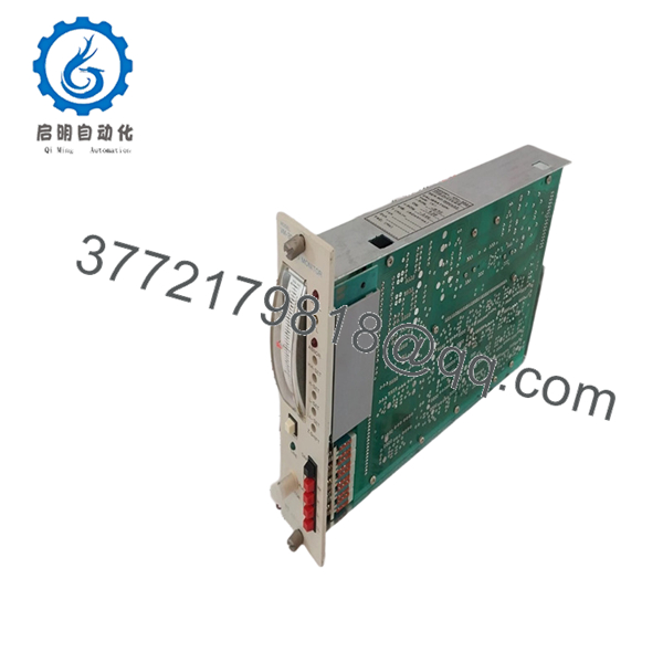
4. Product Introduction
The SHINKAWA VM-3D2 is a thrust (axial position) monitoring module used in VM-3 series machinery protection systems. It processes signals from eddy-current probes to monitor shaft axial movement, a critical parameter in turbines and compressors.
In real plant environments, this module is part of turbine supervisory instrumentation (TSI). It provides continuous measurement and alarm outputs to prevent thrust bearing damage. Although the VM-3 platform is discontinued, it remains widely installed in legacy power and petrochemical facilities.

- VM-3D2
- VM-3D2
5. Installation & Configuration Guide
Stage 1: Pre-Installation Preparation (10–15 minutes)
- ⚠️ Safety First:
- Coordinate with operations (this often ties into turbine trip logic)
- Place system in maintenance or bypass mode per procedure
- Lock out/tag out control power
- Tools Required:
- ESD wrist strap
- PH1 screwdriver
- Fluke 115 multimeter
- Signal simulator (if available)
- Smartphone (for documentation)
- Data Backup:
- Record alarm setpoints (Alert/Danger thresholds)
- Document probe calibration and scaling
- Photograph slot location and wiring
Stage 2: Removing the Old Module (5–10 minutes)
- Open VM rack front panel
- Identify correct VM-3D2 slot (often multiple similar cards)
- Label BNC and terminal connections
- Remove retaining screws
- Pull module straight out
- ⚠️ Note:
Do not mix up channel wiring. Thrust channels are tied to protection logic—wrong mapping can trigger false trips.
Stage 3: Installing the New Module (10 minutes)
- Apply ESD grounding
- Confirm exact model: VM-3D2 (check suffix if present)
- Configuration Clone (Critical):
- Match alarm thresholds
- Verify scaling (mm vs mils)
- Check relay configuration (fail-safe vs non-fail-safe)
- Insert module into same slot
- Seat firmly into backplane
- Secure screws and reconnect wiring
- Checklist:
- Alarm settings correct
- Probe wiring verified
- Output connections secure
Stage 4: Power-On & Testing (15–25 minutes)
- Pre-check: Verify 24 V DC supply stability
- Power-On Steps:
- Power system
- Confirm module status indicators
- Inject simulated displacement signal (if available)
- Verify 4–20 mA scaling
- Check alarm relay activation points
- ⚠️ Troubleshooting Note:
- Offset error → probe calibration mismatch
- No signal → probe or extension cable fault
- False alarms → incorrect scaling or grounding
6. Frequently Asked Questions (FAQ)
Q1: What exactly does the VM-3D2 monitor?
Axial shaft movement (thrust position). This is critical for protecting thrust bearings in turbines and compressors. If this value drifts beyond limits, you’re looking at mechanical damage.
Q2: Is the VM-3 system still supported?
No. Production ended in 2005 and service support stopped around 2010.
Most sites now rely on spare parts or gradual migration.
Q3: Can I upgrade directly to a newer SHINKAWA system?
Not directly. Migration to VM-5 or VM-7 involves rack replacement, rewiring, and reconfiguration. However, newer systems comply with API 670 and support digital communication.
Q4: What’s the most common failure mode?
- Signal drift due to aging analog components
- Relay contact degradation
- Connector oxidation
I’ve seen units pass basic checks but trigger nuisance trips under load because of drift.
Q5: Why is calibration so critical for this module?
Because thrust limits are tight. A 0.2 mm error can be the difference between normal operation and a turbine trip.
Q6: Can I swap this without recalibration?
You can, but you shouldn’t. Always verify scaling and alarm setpoints. Even identical models can have slight offsets.
Q7: Any field advice before putting it back in service?
- ❗ Simulate full travel range before reconnecting trip logic
- ❗ Verify alarm relays independently
- ❗ Check probe gap voltage before trusting readings


