
 WhatsApp: +86 16626708626
 Email:
  Phone: +86 16626708626
Description
Key Technical Specifications
| Parameter | Value |
| Input Signals | 2-channel Eddy Current Displacement (VK/FK Series) |
| Monitor Range | -1.0 to 0 to +1.0 mm (Standard for Thrust) |
| Accuracy | ±0.5% of Full Scale at 25°C |
| Analog Output | Dual 4-20 mA DC (Max load 500 Ω) |
| Alarm Logic | 8 points (H/L Danger, H/L Alert for both channels) |
| Relay Contact Rating | 250V AC/0.2A, 30V DC/2A (Load Resistance) |
| Power Consumption | Approx. 40 VA (including rack) |
| Operating Temp | 0 to +65 °C (32 to 149 °F) |
| Frequency Response | DC to 0.5 Hz |
| Isolation | /IS0 Option: Isolated Output Card included |
Product Introduction
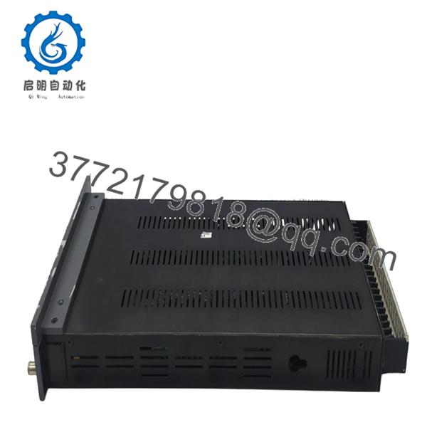
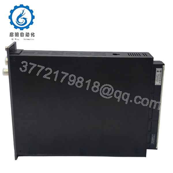
The Shinkawa VM-5T-21012-000-000-001-0-IS0-5G0 is a sophisticated dual-channel thrust monitor designed for critical Turbine Supervisory Instrumentation (TSI). It tracks the axial displacement of high-speed rotating shafts, triggering immediate machine trips if the thrust bearing clearance exceeds safety limits.
Engineers favor this specific configuration because it integrates the IS0 isolated output card, mitigating ground loop interference in complex DCS environments. Built to API 670 standards, the VM-5T provides redundant protection with eight configurable alarm points, ensuring that even minor shaft shifts are detected before mechanical contact occurs.

- VM-5T-21012-000-000-001-0-IS0-5G0
- VM-5T-21012-000-000-001-0-IS0-5G0
Installation & Configuration Guide
Stage 1: Pre-Installation Preparation
- ⚠️ Safety First: Axial thrust trips are “Unit Trip” critical. Ensure all trip logic is bypassed and operations has approved the maintenance window.
- Tools Required: ESD strap, 2.5mm flathead screwdriver, and a calibrated voltage source (-2V to -18V) to simulate probe gapping.
- Data Backup: The long model code indicates a specific factory configuration. Document your existing “Zero” position and voltage offset before removal.
Stage 2: Removing the Old Module
- Loosen the front panel captive screws.
- Pull the module straight out using the handle to avoid lateral stress on the backplane pins.
- Inspect the 50-pin rear connector for any signs of arcing or pin corrosion—common in coastal or high-humidity plants.
Stage 3: Installing the New Module
- ESD Prep: Always wear a grounded strap.
- Configuration Verification: Check the internal DIP switches. For the VM-5T, these control the “Direction” (Direct/Reverse) and the Alarm Reset mode (Auto/Self-hold).
- Gently seat the module into the VM-5G or VM-5W rack until it clicks.
- Secure the screws. This is not just for vibration; it completes the ground path for the module’s shielding.
Stage 4: Power-On & Testing
- Apply power and wait for the “OK” LED.
- Voltage Check: Measure the “Buffered Output” at the front panel using a multimeter. Ensure it matches the probe gap voltage (typically around -10V DC for a centered shaft).
- Alarm Verification: Temporarily adjust the alarm setpoints via the front panel to verify relay transition.
- Dry-run: Confirm the DCS/PLC receives 12mA when the shaft is at the 0.0mm “Zero” position.
Frequently Asked Questions (FAQ)
Q: What does the “IS0” in the model number mean?
A: The “IS0” suffix indicates that this module is equipped with an isolated output card. In my 2 AM troubleshooting sessions, I’ve found this is a lifesaver—it prevents noise from the DCS side from feeding back into the sensitive vibration rack, which often causes “ghost” alarms.
Q: Can I use this for Radial Vibration instead of Thrust?
A: No. While the hardware looks similar to a VM-5V, the internal processing and frequency response (DC to 0.5 Hz) are specifically tuned for slow-moving axial displacement. Using this for vibration will result in zero readings for high-frequency oscillation.
Q: Why does the “OK” LED flash red when I first install it?
A: This usually means the input voltage is outside the “OK window” (typically -2V to -18V). If the shaft is at an extreme position or the probe is disconnected, the monitor will fault to prevent a false trip. Check your field wiring and probe gap.
Q: How do I “Zero” the monitor after installation?
A: The VM-5T allows for a digital or potentiometer-based zero shift. Once the machine is at its mechanical center, use the “ZERO ADJ” on the front panel to bring the display to 0.00mm. This does not change the physical probe gap, only the display and 4-20mA scaling.
Q: Is this module hot-swappable?
A: The VM-5 series supports hot-swapping, but for a Thrust monitor, it is extremely risky. A momentary contact bounce on the backplane can trigger a Danger relay. Always kill the rack power or verify the trip circuit is hard-wired bypassed before pulling a thrust module.


