
 WhatsApp: +86 16626708626
 Email:
  Phone: +86 16626708626
Description
Key Technical Specifications
| Parameter | Value |
| Input Channels | 2 Independent Channels |
| Sensor Types | RTD (Pt100, JPt100) / Thermocouple (K, J, E, T) |
| Measurement Range | -50 to +600 °C (RTD) / -50 to +1,200 °C (Type K) |
| Analog Output | Dual 4-20 mA DC (Isolated) |
| Relay Outputs | 2 Alert, 2 Danger (Configurable logic) |
| A/D Resolution | 16-bit |
| Power Consumption | Approx. 8.0 W |
| Operating Temp | 0 to +65 °C |
| Communication | Internal Bus (VM-7 System) |
| Isolation | 500 V AC between input and output |
Product Introduction
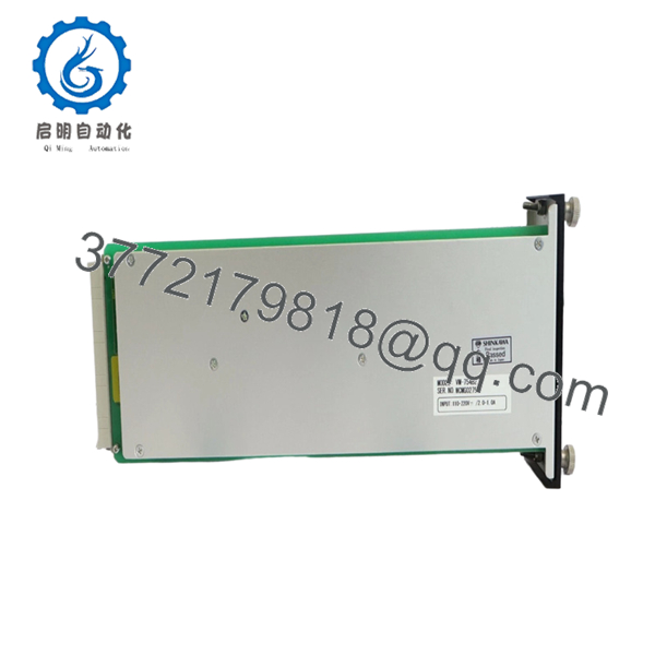
The Shinkawa VM-754B2 is a high-precision dual-channel temperature monitor engineered for the VM-7 series high-density rack system. It is primarily used for monitoring bearing temperatures, stator windings, and exhaust gas temperatures in critical rotating machinery.
The “B2” revision represents the updated hardware design within the VM-7 family, offering improved thermal stability and isolation compared to older legacy units. This module is essential for protecting equipment against thermal runaway or lubrication failure, providing both localized alarm relays and isolated 4-20 mA signals for DCS integration.

- VM-754B2
Installation & Configuration Guide
Stage 1: Pre-Installation Preparation
- ⚠️ Safety First: Ensure all temperature-based trip interlocks are bypassed. Notify the operator that the bearing temperature monitoring for the specific train will be offline during the swap.
- Tools Required: ESD wrist strap, small flat-head screwdriver, and a calibrated temperature simulator (RTD/TC calibrator).
- Data Backup: Use the VM-771B/VM-772B Configurator software to back up the current module settings, including sensor type, lead wire resistance compensation, and alarm setpoints.
Stage 2: Removing the Old Module
- Disconnect the green Phoenix terminal connectors from the rear of the rack.
- Loosen the two captive thumb screws on the front panel of the VM-754B2.
- Pull the module straight out using the handle.
- ⚠️ Note: Check the rack backplane pins for any dust or debris. Since temperature signals are low-voltage (mV levels for TCs), a clean connection is vital.
Stage 3: Installing the New Module
- ESD Prep: Ground yourself. The VM-7 series utilizes high-density CMOS components that are extremely sensitive to static.
- Configuration Check: While the VM-754B2 is primarily software-configured, check any internal hardware jumpers used for input type selection (RTD vs. TC) if applicable to your specific hardware revision.
- Slide the module into the rack and ensure it is fully seated against the backplane.
- Secure the front screws firmly.
Stage 4: Power-On & Testing
- Apply power and confirm the “OK” LED is green.
- Software Upload: Connect your PC to the VM-7 rack service port and upload the configuration file to the new module.
- Sensor Check: Verify the displayed temperature matches the ambient or known process temperature.
- Calibration: Use a simulator to inject a signal (e.g., 100.0 Ω for 0°C on a Pt100). Verify the DCS reads 4.00 mA and the front panel displays the correct value.
Frequently Asked Questions (FAQ)
Q: Can I mix an RTD on Channel 1 and a Thermocouple on Channel 2?
A: In most VM-754B2 configurations, both channels must be set to the same input group (either both RTD or both TC) due to the internal A/D converter scaling. Check the software configuration options; if the “Sensor Type” dropdown allows individual selection, ensure your terminal wiring matches the specific pinout for that sensor.
Q: Does the module compensate for RTD lead wire resistance?
A: Yes. The VM-754B2 supports 3-wire RTD configurations which automatically compensate for lead wire resistance. For 2-wire setups, you’ll need to install a jumper at the terminal block, though I strongly advise against 2-wire for critical bearing protection due to accuracy loss.
Q: Why is my temperature reading drifting or jumping sporadically?
A: This is a common field issue usually caused by a loose shield or a ground loop. Ensure the sensor shield is grounded only at the VM-7 rack end. Also, check the “Burnout” setting in the software; if a wire is intermittent, the module may be trying to drive the signal to a full-scale “Upscale Burnout” state.
Q: Is the VM-754B2 backward compatible with VM-754A?
A: The “B” series is the standard replacement for “A” series modules within the VM-7 rack. However, always verify that your current configuration software version supports the B2 hardware revision to ensure all parameters are mapped correctly.
Q: How do I handle a “Danger” alarm that won’t reset?
A: If the temperature has dropped below the setpoint but the alarm persists, the module is likely set to “Latching” (Self-hold) mode. You must issue a reset command via the front panel “RESET” button or the remote reset terminal on the rack power supply.


