
 WhatsApp: +86 16626708626
 Email:
  Phone: +86 16626708626
Description
Key Technical Specifications
- Power Supply: 24 VDC nominal (18–36 V range), 10 W maximum consumption, built-in reverse polarity protection
- Operating Temperature: -15°C to +55°C
- Storage Temperature: -25°C to +70°C
- Protection Rating: IP32 (installed) per DIN 40050, tested to EN 60945
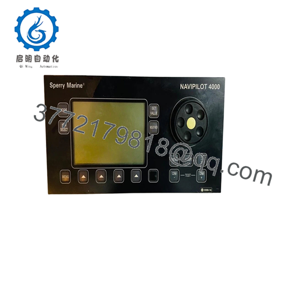
- Control & Display Unit (CDU): Front panel 288 mm x 144 mm, installation depth 150 mm, weight 1.5 kg, graphic LCD with illuminated sealed foil keyboard
- Steering Control Unit (SCU): Dimensions approx. 392–413 mm W x 151–400 mm H x 152–425 mm D, weight 3–4.2 kg
- Heading Inputs: Dual RS-422 (IEC 61162-1), supports HEHDT, HCHDT, HCHDM, HCHDG at 10 Hz; fluxgate magnetic compass sine/cosine
- Rudder Feedback: ±10 V corresponding to ±120° max, 2 kΩ potentiometer
- Steering Outputs: Dual DC solenoid (12–110 VDC, 2 A max) or optional AC solenoid (24–230 VAC, 1 A max); isolated analogue ±10 V or 4–20 mA
- Network: NAVINET 4000 CAN bus (IEC 61162-3), up to 200 m backbone length depending on configuration
- Additional Interfaces: NMEA 0183 speed input, VDR RS-422 output, alarm relay contacts, override inputs
- Compliance: Meets ISO 11674, IEC 62065 (TRACK variants), ISO 16329 (HSC variants), type approved by major classification societies including Germanischer Lloyd (Wheelmark)
Product Introduction
The Sperry Marine NAVIPILOT 4000 is a self-tuning adaptive heading control system used on commercial vessels, cruise ships, and high-speed craft. It processes heading data from gyro or magnetic compasses and drives the steering gear to maintain course with minimal rudder movement. The system includes the Control and Display Unit (CDU) for operator interface and the Steering Control Unit (SCU) for processing and output control.
Field experience on large vessels shows the adaptive algorithm adjusts automatically to changes in load, speed, and weather. Operators select rate, radius, or rudder limit control modes. The NAVINET 4000 CAN bus simplifies integration with manual steering systems like NAVIGUIDE 4000 and external navigation equipment. Many plants still run these units reliably years after production ended in 2018, but verify firmware and product key compatibility with your existing installation before ordering.

- NAVIPILOT 4000
Installation & Configuration Guide
Stage 1: Pre-Installation Preparation (30–45 minutes) ⚠️ Safety First: Notify bridge and engine control of planned downtime. Place steering system in manual mode. Lock out and tag out power to the autopilot rack. Wait at least 5 minutes for capacitors to discharge. Tools Required: ESD wrist strap, PH1/PH2 screwdriver, digital multimeter, wire labels, camera for documentation. Data Backup: Photograph all DIP switch and jumper settings on the SCU. Record current firmware version and product key data. Export any configurable parameters via the CDU service menu if accessible. Document all wiring terminations and heading source connections.
Stage 2: Removing the Old Module (15–20 minutes)
- Remove the front cover or bezel from the CDU and SCU enclosures.
- Label every wire and terminal before disconnection. Do not force connectors.
- Release rack or panel locking tabs and pull the unit straight out to avoid damaging backplane or CAN bus pins.
- Inspect the mounting location for corrosion, bent pins, or dust buildup. Clean if necessary. ⚠️ Keep the old unit intact as a reference until the replacement runs without faults.
Stage 3: Installing the New Module (20–30 minutes)
- Ground yourself with an ESD strap. Confirm the replacement model and part numbers (e.g., CDU 074856-0000-000 or SCU 074851-0000-000) exactly match requirements.
- Configuration Clone (Critical): Set all jumpers and any configurable switches to match the photographed old unit. Pay close attention to CAN bus termination resistors (120 ohm at each end) and I/O board configurations for solenoid or analogue outputs.
- Slide the unit into the rack or panel until it seats firmly with an audible click. Secure locking tabs.
- Reconnect wiring using the original labels. Torque terminals to manufacturer specifications. Self-Checklist: [ ] Jumpers and terminations match [ ] All wiring secure and correct polarity [ ] Unit fully seated and locked.
Stage 4: Power-On & Testing (20–40 minutes) Pre-Power Check: Use a multimeter to verify no shorts on the 24 VDC rail. Confirm primary and backup supplies are isolated if dual-fed. Power-On Steps:
- Energize the autopilot power only (keep steering gear and field devices isolated initially).
- Observe CDU boot sequence and LEDs. Green status indicators should illuminate without persistent error codes.
- Enter service mode if needed to verify firmware version and product key recognition.
- Perform rudder feedback calibration or zeroing per the installation manual.
- Conduct a dry-run heading change test in manual or limited AUTO mode before returning to full service. ⚠️ Troubleshooting Note: Solid red fault LED often points to product key mismatch or CAN bus termination issue. No communication with heading sensors usually traces to RS-422 wiring or baud rate settings. If the system fails to tune, confirm vessel Tau (time constant) is entered correctly in service setup.
Frequently Asked Questions (FAQ)
Can the NAVIPILOT 4000 be hot-swapped under power? No. Power down the system completely before swapping the SCU or CDU. Live insertion risks damage to the NAVINET CAN bus or backplane. Always follow lockout/tagout procedures.
Is the NAVIPILOT 4000 obsolete, and are these units genuinely new? Yes, production ended in 2018 with limited ongoing spare parts support from the OEM. Units offered here are new surplus or tested refurbished pulled from low-hour decommissioned vessels. Each undergoes functional testing on a simulation rack with power-on self-test, communication checks, and output verification. Test reports and photos available on request.
What is the direct replacement if this model is out of stock? Sperry Marine recommends migration to newer systems such as the NAVIPILOT 4500 series where full support exists. For like-for-like continued operation, verified NAVIPILOT 4000 units remain the most compatible option on legacy vessels. Confirm exact variant (BASIC, TRACK, or HSC) matches your classification society requirements.
Will I lose configuration or steering parameters when swapping the unit? The product key carries licensing data and must transfer or be matched. Most operator settings reside in the CDU and service menus. Photograph and document all parameters beforehand. In many cases the logic and tuning values transfer after proper jumper setup and calibration, but always perform full commissioning checks.
Why is the price lower than current OEM list pricing? These are surplus units from vessel upgrades or fleet rationalization, not current factory production. We test every unit for full functionality rather than selling unverified stock. Pricing reflects availability of obsolete parts while still providing a tested, warrantied solution that avoids full system replacement and associated downtime.
How long is the warranty, and what does it cover? We provide a 1-year warranty from shipment on tested functionality. Coverage includes defects in the tested hardware but excludes damage from improper installation, ESD events, or incorrect configuration. Contact us with your vessel details for compatibility confirmation before purchase.


