
 WhatsApp: +86 16626708626
 Email:
  Phone: +86 16626708626
Description
Key Technical Specifications
| Parameter | Value |
|---|---|
| Manufacturer | Vibro-Meter |
| Product | IPC704 Signal Conditioner |
| Base Ordering Number | 244-704-000-042 |
| Supplied Configuration | A2-B07-C232-D2 |
| Environment Option A2 | Ex i / Intrinsic Safety |
| Transfer Option B07 | pC/bar input → µA/mbar output |
| Input Sensitivity C232 | 232 pC/bar |
| Output Sensitivity D2 | 2 µA/mbar |
| Power Supply | 18 to 30 VDC |
| Maximum Supply Current | 25 mA |
| Input Type | Piezoelectric dynamic pressure transducer |
| Input Dynamic Range | 100,000 pC peak |
| Output Transmission | 2-wire current transmission |
| Maximum Dynamic Output | ±5 mA peak |
| Standing Output Current | 12 mA ±0.5 mA |
| Linearity Error | ≤0.2% |
| Temperature Stability | 100 ppm/°C typical |
| Operating Temperature | −30 to +85°C |
| Storage Temperature | −40 to +85°C |
| Humidity | Maximum 95% non-condensing |
| Standard Protection | IP40 |
| Ex i Certifications | ATEX, IECEx, CCSAUS, NEPSI, KGS |
| Standard Housing Weight | 170 g standard; 250 g Ex version |
| Input/Output Terminals | Three screw terminals each, 2.5 mm² maximum wire section |
The IPC704 is designed for piezoelectric transducers and converts their charge-based signal into either a current or voltage signal for transmission to processing electronics. The published documentation specifies 18–30 VDC supply, 25 mA maximum current, ≤0.2% linearity error, and a 100,000 pC peak input dynamic range.
For the A2 configuration, the OEM documentation identifies intrinsic-safety protection and lists ATEX, IECEx, CCSAUS, NEPSI, and KGS certifications. Certification details and special conditions of safe use must be checked against the applicable certificate before installation in a hazardous area.
Product Introduction
The Vibro-Meter IPC704 244-704-000-042-A2-B07-C232-D2 is a piezoelectric signal conditioner configured for dynamic pressure measurement. Its B07 transfer unit accepts a pC/bar sensor signal and provides a µA/mbar output. The A2 option identifies the intrinsically safe version for hazardous-area applications.
The supplied C232/D2 configuration specifies 232 pC/bar input sensitivity and 2 µA/mbar output sensitivity. IPC704 units also provide configurable filtering and RFI protection; however, the E and F filter selections are not included in the abbreviated part number supplied here.
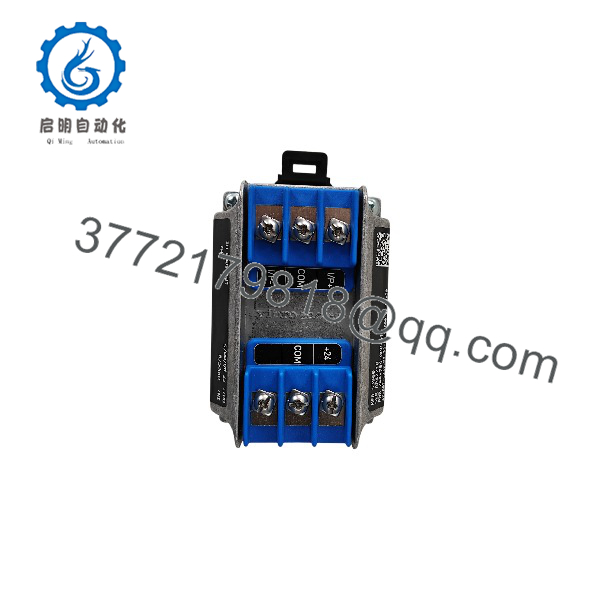
IPC704 244-704-000-042
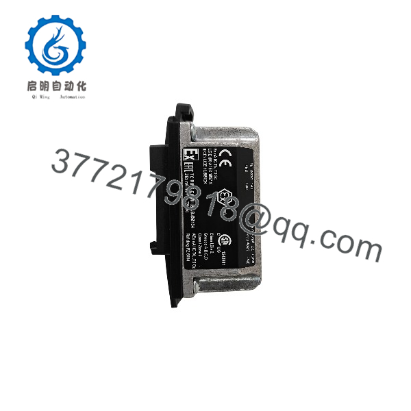
IPC704 244-704-000-042
Installation & Configuration Guide
Stage 1: Pre-Installation Preparation — 5–10 minutes
⚠️ Safety First: This is an A2 intrinsic-safety configuration. If installed in a hazardous location, follow the site’s approved hazardous-area maintenance procedure and the applicable Ex certificate. Do not treat an Ex-rated component as interchangeable solely because the electrical signal appears compatible. The OEM documentation specifies special conditions for safe use that depend on the protection mode.
Tools Required:
- ESD wrist strap
- PH1 screwdriver where applicable
- Digital multimeter
- Wire labels
- Smartphone or camera
- Approved torque screwdriver if the installation specifies terminal torque
Data Backup:
- Photograph the existing IPC704 from every side before removal.
- Record the complete part number, including E through I options.
- Photograph all input and output wiring.
- Record the connected pressure transducer model and sensitivity.
- Record the existing filter configuration.
- Record the receiving DCS/PLC input scaling.
- Verify whether the installation uses a GSI galvanic separation unit.
⚠️ Do not replace this unit from “244-704-000-042” alone. The ordering code determines the signal transfer, sensitivity, filters, installation arrangement, and cable fittings.
Stage 2: Removing the Old Module — 5 minutes
- Place the process in the site’s approved maintenance state.
- Isolate power according to the plant procedure.
- Verify the absence of hazardous voltage before handling the wiring.
- Label the sensor input conductors and output conductors.
- Photograph the terminal arrangement.
- Disconnect the sensor and output wiring without stressing the terminals.
- Remove the mounting screws or mounting hardware.
- Remove the IPC704 and retain it for configuration comparison.
⚠️ Do not discard the original unit immediately. On legacy vibration and pressure measurement chains, the old module is often the quickest way to identify an undocumented filter or sensitivity setting.
Stage 3: Installing the New Module — 5–10 minutes
- Wear an ESD wrist strap and verify the replacement part number.
- Confirm A2 is appropriate for the hazardous-area installation.
- Confirm B07 matches the pressure measurement chain.
- Confirm C232 matches the connected transducer’s sensitivity.
- Confirm D2 matches the required output scaling.
- Verify the missing E/F/G/H/I selections against the original unit.
- Mount the in the same physical orientation.
- Reconnect the input wiring exactly as photographed.
- Reconnect the output and 24 VDC wiring.
- Secure the wiring and verify that no conductor is under mechanical stress.
Self-Checklist:
- A2 hazardous-area configuration verified
- B07 transfer unit verified
- C232 input sensitivity verified
- D2 output sensitivity verified
- HP filter verified
- LP filter verified
- Housing/mounting option verified
- Cable fittings verified
- Sensor polarity verified
- Output wiring verified
Stage 4: Power-On & Testing — 10–15 minutes
- Before energizing, inspect the wiring for shorts and incorrect polarity.
- Verify the available supply is within 18–30 VDC.
- Energize the according to the approved procedure.
- Confirm the current output has the expected quiescent behavior.
- Apply a controlled pressure/vibration input where practical.
- Verify the output changes in the correct direction.
- Confirm the DCS/PLC engineering-unit scaling.
- Compare the indicated value with the calibrated reference instrument.
- Check the signal for excessive noise or clipping.
- Record the final measured input and output values.
The uses a 2-wire current transmission configuration with a 12 mA ±0.5 mA standing current and a maximum dynamic signal of ±5 mA peak. The actual measurement-chain response depends on the selected transfer unit, input sensitivity, output sensitivity, and filter settings.
⚠️ Critical: Do not perform a live hazardous-area replacement simply because the is marked A2. The complete installation must satisfy the applicable intrinsic-safety system requirements, including associated equipment, wiring, barriers/separators, and certificate conditions.
Frequently Asked Questions (FAQ)
Q1. What does the Vibro-Meter 244-704-000-042-A2-B07–D2 do?
It conditions the charge signal from a piezoelectric dynamic pressure transducer and converts it into a current output suitable for transmission to monitoring or control electronics. B07 specifies the pC/bar-to-µA/mbar transfer configuration.
Q2. What does A2 mean on this ?
A2 identifies the Ex i intrinsic-safety version. The OEM documentation lists ATEX, IECEx, CCSAUS, NEPSI, and KGS certification information for the applicable Ex configurations. Always check the current certificate and installation conditions before using the unit in a hazardous location.
Q3. What does B07–D2 mean?
B07 defines the transfer unit as pC/bar input to µA/mbar output. specifies a 232 pC/bar transducer sensitivity. D2 specifies the selected output sensitivity as 2 µA/mbar.
Q4. Is the part number complete if it ends with D2?
Not for a complete ordering description. The OEM ordering structure continues through E, F, G, H, and I. These selections determine the high-pass filter, low-pass filter, installation arrangement, and input/output cable fittings.
For procurement, I would request a photo of the actual nameplate and the remaining suffix information rather than assuming those options.
Q5. Can I replace another with this unit directly?
Only after checking the complete configuration. Two units can share the same base number 244-704-000-042 while having different transfer units, sensor sensitivities, output sensitivities, filters, mounting arrangements, or cable fittings. A visually identical replacement can therefore produce the wrong measurement scaling.
Q6. Does the require a separate galvanic isolation unit?
The OEM documentation states that dynamic pressure transducers should always be used with a GSI galvanic separation unit when using the 3-wire voltage-output arrangement. For the 2-wire current-transmission configuration, the documented current modulation arrangement can transmit up to 1 km when a GSI galvanic separation unit is used. Check the actual measurement-chain architecture before removing or bypassing a GSI.
Q7. Is this new, surplus, or refurbished?
The part number alone does not establish physical condition. A supplier should state whether the actual unit is New Original, New Surplus, or Refurbished/Tested and provide photographs of the actual item. For a safety-related A2 installation, I would also request the nameplate, serial information, applicable certification documentation, and a functional test record before acceptance.



