
 WhatsApp: +86 16626708626
 Email:
  Phone: +86 16626708626
Description
Key Technical Specifications
| Parameter | Value |
|---|---|
| Product Type | Universal Analog Input Module |
| Compatible PLC | Allen-Bradley SLC 500 |
| Manufacturer | Spectrum Controls (Allen-Bradley Compatible) |
| Model Number | 1746SC-NI8U |
| Input Channels | 8 configurable channels |
| Supported Inputs | Voltage, Current, Thermocouple, RTD, Resistance |
| Voltage Ranges | ±50 mV, ±100 mV, ±0.5 V, ±2 V, 0–5 V, 1–5 V, 0–10 V, ±10 V |
| Current Ranges | 0–20 mA, 4–20 mA |
| Thermocouple Types | J, K, T, B, E, R, S, N, C |
| RTD Support | PT385, PT3916, Ni618, Ni672, Cu426 |
| Electrical Isolation | 500 V DC field-to-backplane |
| Backplane Current | 120 mA @ 5 V DC, 100 mA @ 24 V DC |
| Power Dissipation | 3.0 W maximum |
| Operating Temperature | 0 to 60 °C |
| Storage Temperature | −40 to 85 °C |
| Relative Humidity | 5–95% non-condensing |
Product Introduction
The A-B 1746SC-NI8U is a universal analog input module designed by Spectrum Controls for Allen-Bradley SLC 500 PLC platforms. It installs directly into a standard 1746 I/O chassis and supports voltage, current, thermocouple, RTD, and resistance measurements from a single module.
From a maintenance standpoint, this module eliminates the need for multiple dedicated analog cards. Each channel can be configured independently, making it well suited for retrofit projects where different sensor types share the same PLC rack. Automatic calibration and programmable digital filtering help maintain measurement accuracy in industrial environments.
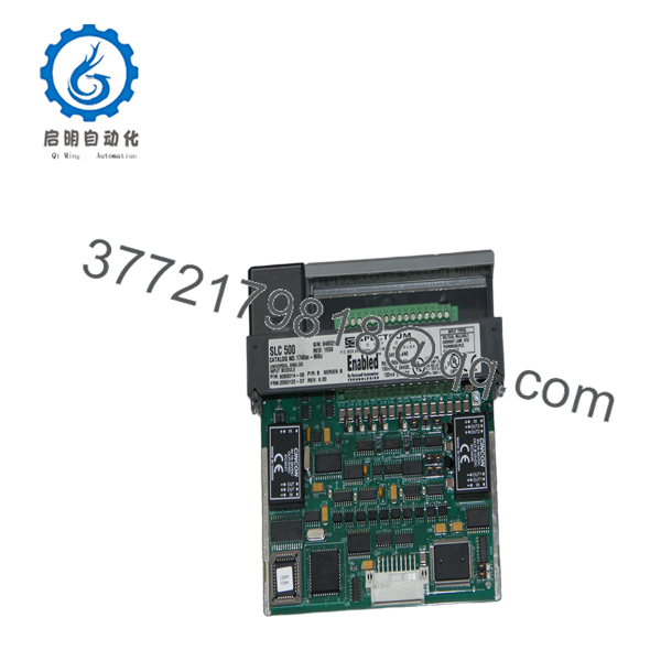
1746SC-NI8U
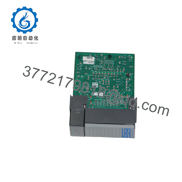
1746SC-NI8U
Installation & Configuration Guide
Stage 1 – Pre-Installation Preparation (Estimated Time: 10 Minutes)
⚠️ Safety First
- Notify operations personnel of the planned shutdown.
- Bring the controlled equipment to a safe operating state.
- Apply lockout/tagout procedures.
- Remove chassis power and wait at least 5 minutes before opening the cabinet.
Tools Required
- Grounded ESD wrist strap
- PH1 screwdriver
- Fluke 115 digital multimeter
- Wire identification labels
- Smartphone for wiring documentation
Data Backup
- Upload the RSLogix 500 project.
- Save the processor program and I/O configuration.
- Record channel scaling, filter settings, and engineering units.
- Photograph terminal wiring and any jumper configuration.
Stage 2 – Removing the Existing Module (Estimated Time: 10 Minutes)
- Verify the chassis is de-energized.
- Label every field wire.
- Remove the detachable terminal block.
- Release the module retaining tabs.
- Pull the module straight out without twisting.
- Inspect the backplane connector for bent pins, contamination, or oxidation.
⚠️ Do not discard the original module until commissioning has been completed successfully.
Stage 3 – Installing the Replacement Module (Estimated Time: 10 Minutes)
- Connect your ESD strap before handling the module.
- Verify the replacement catalog number is 1746SC-NI8U.
- Inspect the connector and guide rails.
- Insert the module until the locking tabs engage.
- Reinstall the terminal block.
- Restore all field wiring.
- Configure each input channel using RSLogix 500 according to the connected sensor type.
Self-Checklist
- Correct module installed
- Wiring verified
- Module fully seated
- Terminal block secured
- Channel configuration restored
Stage 4 – Power-Up & Functional Testing (Estimated Time: 15 Minutes)
Pre-Power Checks
- Measure the 24 V DC control supply.
- Verify shield grounding.
- Check for wiring shorts.
Commissioning Steps
- Energize the SLC 500 chassis.
- Confirm normal module status.
- Verify the processor recognizes the module.
- Review configuration words in RSLogix 500.
- Simulate every analog input.
- Verify engineering values against a calibrated signal source.
⚠️ Troubleshooting Notes
- Configuration fault: Confirm jumper settings and channel configuration match the installed sensor type.
- Incorrect readings: Verify thermocouple type, RTD selection, scaling, and wiring polarity.
- No communication: Confirm the module is fully seated and backplane power capacity has not been exceeded.
Common Field Pitfalls
❗ Firmware and Project Configuration
Although this module does not contain user logic, configuration data stored in the SLC processor must match the installed hardware. I’ve seen maintenance teams replace the hardware correctly, only to spend hours troubleshooting because the controller project still referenced different channel settings.
❗ Jumper Configuration
This is one of the easiest mistakes to make. The 1746SC-NI8U uses internal jumpers to define certain input paths for current, voltage, and RTD operation. Before installing a replacement, compare the jumper positions with the original module. A five-minute inspection can prevent several hours of troubleshooting.
❗ Sensor Wiring
Never assume two temperature sensors use identical wiring. Three-wire and four-wire RTDs require different terminal assignments, while thermocouples require the correct extension wire and polarity. Wire according to the manual, not from memory.
❗ Chassis Power Budget
The module draws approximately 120 mA at 5 V DC and 100 mA at 24 V DC from the SLC backplane. Calculate total chassis loading before adding or replacing modules. Leave at least a 20% capacity margin whenever possible.
❗ Electrostatic Discharge
Always use an ESD wrist strap and grounded work surface. I’ve watched perfectly good analog modules become intermittent after being handled on a dry winter day without proper grounding. Those failures are difficult to diagnose because they often appear only after the system warms up.
Keep these checks in mind and you’ll avoid most of the rework that follows analog module replacements.
Frequently Asked Questions (FAQ)
Q1. Is the A-B 1746SC-NI8U manufactured by Allen-Bradley?
Not directly. The 1746SC-NI8U is manufactured by Spectrum Controls, a long-established supplier of compatible I/O products for Allen-Bradley platforms. It is designed specifically for installation in Allen-Bradley SLC 500 systems and is supported within the Rockwell Automation ecosystem through the Encompass Partner program.
Q2. Can I mix voltage, current, and thermocouple inputs on one module?
Yes. Individual channels can be configured independently for different supported input types. This flexibility is the primary reason many retrofit projects select the 1746SC- instead of several dedicated analog modules.
Q3. Can the module be replaced while the PLC is powered?
No.
The SLC 500 platform does not support hot-swapping for this module. Remove power before replacement to avoid damaging the backplane or corrupting I/O communications.
Q4. Is the 1746SC- obsolete?
Yes.
The SLC 500 product family is a legacy platform, and the 1746SC- is considered a discontinued product. New surplus inventory and tested replacement units remain available through industrial automation suppliers, but long-term availability is limited.
Q5. Will replacing this module erase my PLC program?
No.
The ladder logic resides in the SLC processor. However, always keep a backup of the RSLogix 500 project because channel configuration, scaling, and documentation are essential during commissioning.
Q6. Why are New Surplus units often less expensive than OEM list price?
Many available units originate from unused project inventory, plant expansions that were never commissioned, or warehouse surplus. Lower pricing usually reflects lifecycle status rather than product capability. Request the inspection report, functional test documentation, and warranty details before purchasing.
Q7. What should I verify before installing a replacement?
Verify:
- Exact catalog number (1746SC-)
- Chassis power budget
- Jumper configuration
- Sensor types
- Wiring layout
- RSLogix 500 channel configuration
- Shield grounding
Those seven checks prevent the majority of commissioning issues encountered during SLC 500 analog I/O replacements.



