
 WhatsApp: +86 16626708626
 Email:
  Phone: +86 16626708626
Description
2. Product Core Brief
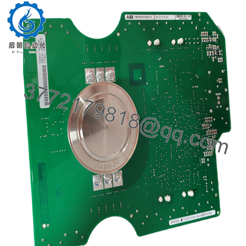
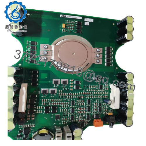
- Model: 5SHX0660F0001 3BHB003387R0101
- Brand: ABB
- Series: High-Power Press-Pack IGBT & Diode Stack
- Core Function: Medium-Voltage Power Conversion Stack
- Product Type: Paired IGBT + Diode Power Module Assembly
- Key Specs: MV press-pack IGBT + press-pack diode; kV-class voltage; kA nominal current
- Condition: New Original / New Surplus
3. Key Technical Specifications
| Parameter | Value |
|---|---|
| ABB IGBT Part | 5SHX0660F0001 |
| ABB Diode Part | 3BHB003387R0101 |
| Module Type | Press-Pack IGBT + Press-Pack Diode Stack |
| Voltage Class | kV-class (verify exact rating per OEM datasheet) |
| Current Rating | kA-class continuous (application dependent) |
| Device Technology | Press-Pack IGBT / Press-Pack Fast Recovery Diode |
| Cooling | External heat sink / liquid or forced air |
| Operating Temp | Typically −40 °C to +125 °C junction (confirm datasheet) |
| Mounting | Clamped assembly between heat sinks |
| Application | Medium-Voltage drives, converters |
| Standards | IEC 60747 semiconductor compliance |
| Terminal Type | Stud or bolted press-pack connections |
⚠️ Always confirm exact voltage and current ratings against the official ABB datasheet for your specific drive platform. This assembly is designed for medium-voltage power conversion where thermal and mechanical stresses are significant.

- 5SHX0660F0001 3BHB003387R0101
4. Product Introduction
The ABB 5SHX0660F0001 + 3BHB003387R0101 assembly is a paired press-pack IGBT and diode stack designed for medium-voltage power conversion applications, such as MV variable-frequency drives and industrial rectifiers. The press-pack format offers high transient ruggedness and uniform thermal cycling performance under high power loads.
Engineers choose this module set where high voltage and current handling with reliable switching and recovery characteristics are required. The IGBT and diode combination forms the core of a high-power inverter or converter leg. As with all press-pack power stacks, proper heat-sink clamping and cooling are essential for predictable lifetime performance.
5. Installation & Configuration Guide
Due to high stored energy and stringent mechanical requirements, install these components with disciplined procedures and proper safety controls.
Stage 1: Pre-Installation Preparation (10–20 minutes)
⚠️ Safety First
- Schedule a controlled outage; isolate all AC mains and DC bus supplies.
- Lock out/tag out (LOTO) and discharge DC link capacitors fully; verify with a high-voltage meter.
- Wear ESD protection and appropriate HV PPE.
Tools Required
- ESD wrist strap
- Insulated torque wrench and socket set
- DC high-voltage meter + probes
- Heat-sink surface cleaner (isopropyl alcohol)
- Labels and smartphone for documentation
Documentation
- Photograph existing stack orientation, bus bar alignment, and terminal connections.
- Note cooling arrangements (fan or liquid lines).
Stage 2: Removing the Old Stack (10–15 minutes)
- Verify zero voltage on DC link and AC mains using HV meter.
- Label all connections (IGBT gate, diode terminals, thermocouples).
- Loosen clamping bolts in cross pattern to release press-pack compressive force evenly.
- Remove press-pack modules straight out — no twisting or prying.
- Inspect heat-sink surfaces for flatness and debris; clean as needed.
⚠️ Press-pack modules require even contact pressure; uneven removal can distort heat-sink surfaces.
Stage 3: Installing the New Stack (15–20 minutes)
- ESD & Cleanliness: Wear wrist strap; clean heat-sink faces thoroughly.
- Part Verification: Confirm 5SHX0660F0001 and 3BHB003387R0101 match site BOM.
- Position diode and IGBT in correct sequence per schematic (anode/cathode orientation critical).
- Apply calibrated clamping force evenly using torque wrench to OEM spec.
- Reconnect bus bars, gate drivers, and sensors per original labels.
Self-Checklist
- Both part numbers confirmed
- Heat-sink surfaces cleaned & flat
- Clamping force even to spec
- Terminals and sensors properly attached
Stage 4: Power-On & Testing (20–30 minutes)
- Restore AC mains and DC link in controlled sequence per OEM procedures.
- Monitor DC link voltage and system protections.
- Observe drive diagnostics for IGBT and diode health indicators.
- Conduct controlled load tests to validate power stage performance.
⚠️ If the drive faults (overcurrent, under-voltage, gate driver errors), de-energize immediately and verify wiring, clamping, and cooling setup.
6. Frequently Asked Questions (FAQ)
Q1: Are these two separate parts or a matched set?
They are often sold as a matched press-pack IGBT (5SHX0660F0001) and fast-recovery diode (3BHB003387R0101) stack for medium-voltage power stages. In drive assemblies, they operate together as complementary elements.
Q2: Is this assembly hot-swappable?
No. Press-pack power stacks must be replaced with the power off and DC link discharged. Hot-swapping risks arc flash and catastrophic failure.
Q3: What does “New Original / New Surplus” mean?
Indicates unused factory-manufactured OEM stock, typically sourced from surplus or excess inventory. Components have not been installed but may show age in packaging. Ask for traceability and photos.
Q4: Do I need new cooling when replacing?
Confirm existing cooling (fans or liquid) is functioning and sized appropriately. Press-pack power stacks dissipate significant heat; degraded cooling shortens life.
Q5: Why might my price be lower than OEM list?
Surplus inventory pricing often undercuts OEM list due to market availability. Always verify authenticity, condition, and traceability before procurement.
Q6: What’s the most common installation pitfall?
Uneven clamping force and unclean heat-sink surfaces are the top causes of high thermal resistance and premature failures. Always clean heat-sink faces and apply correct torque evenly.


