
 WhatsApp: +86 16626708626
 Email:
  Phone: +86 16626708626
Description
- Key Technical Specifications
- Blocking voltage (V_DRM / V_RRM): 3300 V (asymmetric, typical for this class)
- Turn-off current (I_TGQM): up to ~660 A (application and cooling dependent)
- On-state voltage (V_T): typically 2.0–2.5 V at nominal current
- Reverse conducting current: Integrated diode handles freewheeling
- dv/dt immunity: > 2000 V/µs
- di/dt capability: > 1000 A/µs
- Operating junction temperature: -40°C to +125°C (max)
- Storage temperature: -40°C to +125°C
- Mounting: Press-pack, requires clamping force (typically 8–12 kN axial)
- Diameter / Size: 51 mm / 68 mm wafer class (press-pack housing)
- Weight: ≈ 1.5–2.5 kg
- Cooling: Forced air or liquid (heat sink required)
- Gate unit: Requires compatible driver (e.g., 3BHE022333R0101 or equivalent series)
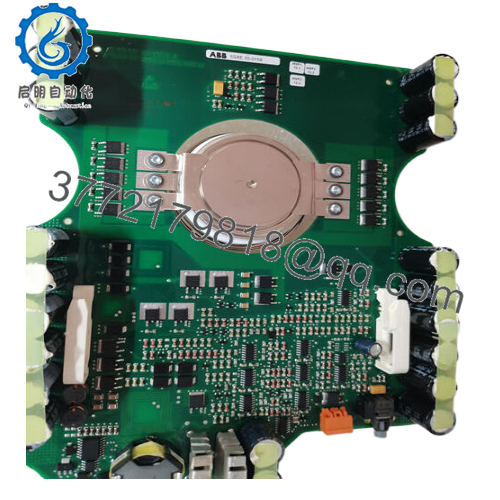
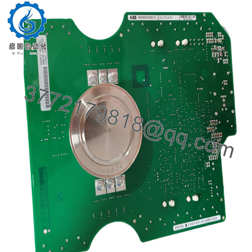
- Product Introduction The ABB 3BHB018104R0001 (type 5SHX0660F0002) is a reverse-conducting IGCT module designed for medium-voltage variable frequency drives, primarily in the ACS5000 series. It functions as the main switching element in inverter legs where regenerative capability or bidirectional power flow is needed.
In practice, the RC-IGCT design eliminates the need for separate freewheeling diodes in certain topologies, reducing stack size, conduction losses, and heat dissipation compared to standard IGCT + diode pairs. Engineers choose it for 2.3–4.16 kV drive systems prioritizing reliability and efficiency over ultra-high switching frequency.

- 5SHX0660F0002 3BHB018104R0001
- Installation & Configuration Guide
Stage 1: Pre-Installation Preparation (≈ 20–45 minutes) ⚠️ Safety First: Lock out/tag out all incoming power to the drive cabinet. Discharge DC link capacitors fully (wait ≥5 minutes; verify <50 V with multimeter on bus bars). Notify operations for scheduled downtime. Tools Required: Grounded ESD wrist strap, torque wrench/load cell for clamp, multimeter, insulation tester, smartphone/camera, approved thermal compound, clean cloths. Data Backup: Photograph gate driver connections, fiber optics, clamp assembly, and stack positioning. Note any snubber or resistor configurations. No software logic backup required—this is a power device.
Stage 2: Removing the Old Module (≈ 20–50 minutes)
- Confirm zero energy state on DC bus and control power.
- Disconnect gate fibers, power connections, and any cooling interfaces (label if needed).
- Loosen press-pack clamp bolts evenly in a cross pattern to prevent tilting or binding.
- Extract the IGCT module/stack straight out—protect gate contacts and avoid damaging wafer surfaces. ⚠️ Inspect old module for burn marks, arcing, or discoloration (document with photos for potential claims).
Stage 3: Installing the New Module (≈ 40–70 minutes)
- Ground with ESD strap. Confirm new unit markings match 5SHX0660F0002 exactly.
- Clean anode/cathode surfaces with isopropyl alcohol; apply thin thermal compound layer if OEM manual specifies.
- Align module in stack, ensure proper gate contact and fiber seating.
- Reassemble clamp and apply torque/clamping force per ABB spec (typically 8–12 kN—use calibrated tool). Self-Checklist: [ ] Clamping force verified, [ ] Contacts clean/aligned, [ ] Fibers/gate secure, [ ] No debris in stack.
Stage 4: Power-On & Testing (≈ 60–120 minutes) Pre-Power Check: Verify no shorts on gate circuit or DC bus; measure insulation resistance (>100 MΩ at 500 V). Power-On Steps:
- Apply control power first—check gate driver LEDs for ready/no-fault status.
- Ramp up DC link voltage gradually (monitor current).
- Observe gate unit indicators: green healthy; red/flashing for faults (overvoltage, overtemperature, commutation fail).
- Run drive in no-load or low-power test mode—verify switching and minimal heat rise.
- Progress to full-load test under supervision; monitor junction temp via driver feedback. ⚠️ Troubleshooting Note: Solid fault LED often from insufficient clamp force or gate fiber polarity error—recheck torque and connections. Commutation issues? Verify driver firmware and stack alignment.
- Frequently Asked Questions (FAQ)
Can this RC-IGCT be hot-swapped? No. Full power-down and DC link discharge are mandatory. Live handling risks explosion-level failure due to high energy stored in the bus—always isolate and verify zero voltage.
Is the 5SHX0660F0002 obsolete, and is your stock genuinely new? It’s a mature design (still in service on many ACS5000 installations), but new production is phased out or limited. We supply new surplus/original from verified channels. Units get full inbound checks (traceability, visual, no rework signs), powered gate/driver test, 24+ hour burn-in simulation, and insulation/continuity verification. Photos/videos of testing available on request.
What is the direct replacement if this is out of stock? No exact drop-in due to wafer size (51 mm class), RC design, and press-pack specs. ABB may direct to upgraded IGCT variants or full phase module kits—check current supersession via ABB service. In practice, tested surplus or refurbished units are the fastest fix without redesign.
Will swapping the IGCT require drive reprogramming? No—control parameters and logic remain in the drive controller. But verify gate driver firmware matches, and retune commutation/regulation if on-state voltage varies slightly from the old unit.
Why is your price lower than ABB factory list? This is new surplus stock (unused, original from excess/project decommissioning), not current OEM production runs. We perform independent functional and electrical testing but bypass factory distribution costs. For safety-critical or certified installations, cross-reference with ABB marine/industrial service for any implications.


