
 WhatsApp: +86 16626708626
 Email:
  Phone: +86 16626708626
Description
Key Technical Specifications
| Parameter | Value |
|---|---|
| Manufacturer | ABB |
| Part Number | 6263246 |
| Series | S800A |
| Product Type | Universal I/O module |
| Nominal Supply Voltage | 24 V DC |
| Listed Power Consumption | 2 W |
| Total I/O Points | 16 |
| Analog Inputs | 8 channels |
| Analog Input Types | 0–10 V, 4–20 mA |
| Analog Outputs | 4 channels |
| Analog Output Types | 0–10 V, 4–20 mA |
| Digital Inputs | 4 channels |
| Digital Outputs | 4 channels |
| Listed Analog Response Time | Less than 10 ms |
| Listed Digital Response Time | Less than 1 ms |
| Listed Analog Accuracy | 0.1% of full scale |
| Mounting | DIN rail |
| Listed Environmental Rating | IP67 |
| Listed Dimensions | 90 × 35 × 25 mm |
| Listed Weight | 0.1 kg |
A third-party product page identifies ABB 6263246 as an S800A universal I/O module and lists 16 total I/O points with mixed analog and digital channels. ABB OEM documentation was not available in the retrieved sources, so treat voltage ranges, accuracy, IP rating, dimensions, and channel allocation as listing-provided data that must be verified against the unit label and ABB documentation before installation.
Product Introduction
The ABB 6263246 is listed as an S800A universal I/O module for interfacing analog and digital field devices with an automation controller. The module is described as accepting 0–10 V and 4–20 mA analog signals while supporting digital input and output channels for local machine or process-control applications.
The main reason to select an exact ABB 6263246 replacement is to retain the installed S800A wiring, I/O mapping, and controller configuration. Before ordering, verify the existing module label, channel type, terminal arrangement, hardware revision, and required field-signal ranges. Do not assume a similarly numbered ABB module has the same analog-output or digital-I/O allocation.
Troubleshooting Quick Reference
| Symptom | Possible Cause | Relevance to This Part | Quick Check Method | Recommendation |
|---|---|---|---|---|
| No module status indication | Missing 24 V DC supply, reversed polarity, blown cabinet fuse, loose module connection | ✅ High | Measure the specified 24 V DC supply at the module power terminals using the approved ABB wiring diagram; inspect fuse and terminal torque | Correct the supply issue before replacing the module |
| All I/O channels show fault or zero values | Loss of module power, bus or controller communication fault, incorrect configuration | ✅ High | Check controller diagnostics, I/O bus status, module addressing, and the 24 V DC supply under load | Confirm controller and bus health before declaring a module failure |
| One analog input reads 0 mA or 0 V | Open loop, failed transmitter, field fuse issue, broken cable, wrong channel configuration | ⚠️ Medium | Measure the signal at the module input terminals and at the field transmitter; compare with a calibrated loop source if available | Troubleshoot transmitter and field wiring before replacing the I/O module |
| Analog input reads high or unstable | Incorrect 0–10 V versus 4–20 mA configuration, shield issue, ground loop, sensor fault | ⚠️ Medium | Confirm channel configuration in the controller; measure signal with a Fluke 115 or equivalent meter; inspect shield termination | Correct configuration and grounding before changing the module |
| Analog output does not drive valve positioner or actuator | Open output loop, external load failure, wrong output scaling, failed output channel | ✅ High | Command a known test value, then measure output at the module terminals and at the field device | Check output scaling, load resistance, and field wiring before replacement |
| Digital input remains permanently on or off | Failed proximity switch, wrong common reference, broken input wire, incorrect input type | ❌ Usually Low | Measure field voltage at the input terminal while changing the sensor state; inspect sensor LED and cable | Investigate field device and wiring first |
| Digital output does not energize | Output fuse open, failed relay/solenoid, missing load supply, interlock active, output channel fault | ⚠️ Medium | Confirm output command in controller diagnostics; measure field supply and output voltage at the terminal | Check load circuit and external fuse before replacing the module |
| Module faults after replacement | Incorrect module variant, incompatible terminal base, incorrect channel configuration, wiring mismatch | ✅ High | Compare old and replacement labels, terminal layout, wiring diagram, and controller hardware configuration | Stop and verify compatibility before applying field power |
| Intermittent analog noise | Poor shielding, ground loop, VFD noise, loose terminals, cable routed beside power conductors | ❌ Low to Medium | Inspect shield termination and cable routing; compare signal stability at field source and module terminal | Correct installation practices before replacing the module |
Field warning: Most apparent I/O-module failures turn out to be field faults. A failed 4–20 mA transmitter, blown fuse, loose terminal, incorrect common reference, or cable shield bonded at the wrong end can produce the same symptoms as a bad I/O channel. Measure the signal at the module terminal before pulling the card.
❗ Firmware and configuration mismatch: Record the controller project, module channel configuration, scaling, engineering units, alarm limits, and any calibration values before replacing the module. An I/O module can be electrically healthy and still appear failed when the controller expects a different channel mode or signal type.
❗ Terminal block and wiring compatibility: Take a clear photo of every terminal before removal. Do not wire from memory. Even when an ABB module looks similar, terminal assignment can change between product variants. Verify the terminal base and all field wiring against the approved drawing.
❗ Signal type mismatch: Do not place a 24 V DC discrete signal, a 4–20 mA loop, and a 0–10 V voltage signal onto a channel unless the exact channel configuration supports it. A wrong signal type can damage an input, force an incorrect reading, or cause a process trip.
❗ Power budget: Confirm the 24 V DC power supply remains within specification under normal rack load and startup conditions. The source listing reports 2 W power consumption, but the actual installation must include field loads, adjacent modules, relays, sensors, and supply derating.
❗ ESD precautions: Wear a grounded wrist strap and keep the module in ESD-safe packaging until installation. I have seen a technician unbag an I/O module on a dry shop floor, handle it without a strap, then chase intermittent analog-channel faults for two days. Use the strap.
Keep these checks in mind and you will save yourself 90% of typical rework time. If the issue remains unresolved, provide photos of the module label, terminal block, status indicators, controller diagnostics, and measured field-signal values to technical support.
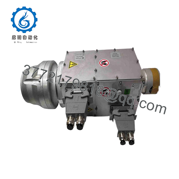
6263246
Frequently Asked Questions
What is ABB 6263246?
ABB 6263246 is listed as an ABB S800A universal I/O module. The available third-party product data describes a mixed-signal module with analog inputs, analog outputs, digital inputs, and digital outputs for industrial control applications.
How many I/O points does ABB 6263246 have?
The available listing states 16 total I/O points: 8 analog inputs, 4 analog outputs, 4 digital inputs, and 4 digital outputs. Confirm this channel allocation on the physical module label and ABB documentation before using it for engineering or procurement.
Does ABB 6263246 accept both 4–20 mA and 0–10 V signals?
The available product listing states that the analog input and output functions support 0–10 V and 4–20 mA signals. The exact channel-by-channel capability, wiring method, common-reference arrangement, load limits, and configuration method require confirmation from ABB documentation for the installed module revision.
Can I hot-swap the ABB 6263246 module?
Do not assume hot swapping is allowed. It depends on the S800A station architecture, terminal-base design, controller configuration, process criticality, and site maintenance procedure. In a live process, removing a module can create false alarms, drop output signals, or force equipment to a fail-safe state. Isolate the appropriate supply and follow the approved lockout/tagout and bypass-management procedure.
Is ABB 6263246 a direct replacement for every I/O module?
No. It may fit the same mounting system while using a different channel mix, field voltage rating, terminal base, bus interface, or configuration profile. Match the exact 6263246 part number and confirm the existing channel types, installed terminal arrangement, and controller project before ordering.
Will my PLC or DCS configuration remain after I replace the module?
Usually, I/O configuration resides in the controller or engineering project, but do not assume every parameter transfers automatically. Record channel modes, scaling, engineering ranges, filter settings, alarm limits, fail-state settings, and any calibration values before removal. If the system supports an engineering backup, make one before replacing the hardware.
Why is a New Surplus ABB 6263246 module less expensive than a factory order?
New Surplus typically comes from unused project inventory, cancelled installations, maintenance stock liquidation, or discontinued-system inventory. It may be unused but not factory sealed. Before buying, request actual label photos, serial-number visibility, terminal and connector photos, storage-condition information, and written warranty terms.
What testing should I request before purchasing?
Ask for a documented test process tied to the exact unit:
- Inbound label and part-number verification against ABB 6263246
- Visual inspection for corrosion, cracked housings, bent contacts, scratches, rework marks, and UV yellowing
- Inspection of the terminal base, connector contacts, DIN-rail latch, and module housing
- Power-up verification using the correct 24 V DC supply and compatible test fixture
- Controller or bus communication check on a compatible ABB setup, where available
- Analog-input simulation using calibrated 4 mA, 12 mA, 20 mA, 0 V, 5 V, and 10 V reference signals
- Analog-output verification into an approved test load
- Digital-input and digital-output functional checks
- Test report, QC sign-off, ESD bagging, protective packing, and a stated warranty
Test videos and photographs should be available upon request. Because the retrieved data comes from a third-party listing rather than an ABB OEM datasheet, verify every critical electrical and mechanical value before installing the module in a production system.



