WhatsApp: +86 16626708626
 Email:
 Phone: +86 16626708626
Description
Core Product Summary
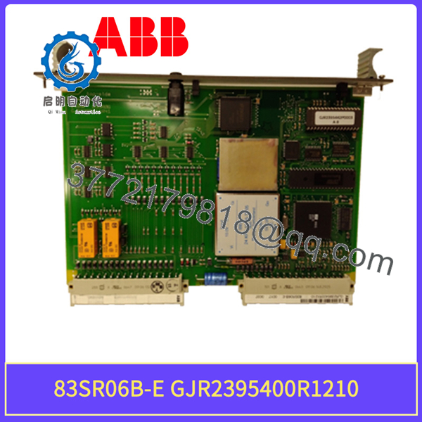
The ABB 83SR06B-E, order number GJR2395400R1210, is the universal control module of ABB’s Procontrol P process control system (P14 hardware line), listed by ABB as an 83SR06 Control Module, universal. It is a stored-program binary and analog control device that operates at the drive, group, and unit control levels of a power plant or process automation system, handling tasks such as drive control for unidirectional drives, actuators and solenoid valves, binary function group control, three-step control, and signal conditioning.
The module plugs into a Procontrol multi-purpose processing station, where its address is set automatically, and communicates over the station bus. Its user program, created from function blocks with the PDDS programming and diagnostic system, is stored in nonvolatile EEPROM and can be loaded and changed online over the bus. The module carries its process inputs and outputs on a 32-pole edge connector (X21) and its station-bus interface plus 24 V and 5 V operating voltages on a 48-pole edge connector (X11), both to DIN 41612.
Key Technical Specifications
| Parameter | Value |
|---|---|
| Product type | Universal control module for stored-program binary and analog control |
| Type designation / order number | 83SR06B-E / GJR2395400R1210 |
| System family | ABB Procontrol P (P14) process control system |
| Control levels served | Drive, group, and unit control |
| Operating modes | Binary control (with analog basic functions), analog control (with binary control), signal conditioning |
| Module cycle time | Binary control: variable, up to 700 ms; analog control: fixed, selectable 50/100/150/200/250 ms |
| Max. drive control functions per module | 4 (e.g., ASE, ASS, ASM, ASI function types) |
| Configuration capacity | Up to 287 module inputs, 223 module outputs, 255 calculated function results, 128 timers, 80 parameters, 16 limit value sets |
| User program storage | EEPROM (structure, address, parameter, limit value, simulation lists); loaded/changed online from PDDS via the bus |
| Operating voltage | USA/USB = 24 V; current consumption IS = 80 mA plus output currents |
| Bus section voltage | UD = 5 V; current consumption ID = 250 mA |
| Power dissipation | 3.5 W |
| Contact voltage for binary inputs | 48 V (US11/US21/US31/US41), ±30 mA per contact |
| Binary input characteristics | 0-signal 0…10.5 V (without monitor) or 6…10.5 V (with monitor); 1-signal 14…51 V; input resistance 10 kΩ; destruction limit >55 V |
| Command outputs | Bx1 (OFF/CLOSED), Bx2 (ON/OPEN), common BVx; ±80 mA, short-circuit-proof and non-interacting |
| Board format | 6 units, 1 division, 160 mm deep |
| Connectors | DIN 41612 edge connectors: X11, 48-pole type F (station bus, operating voltages US and UD); X21, 32-pole type F (process inputs/outputs) |
| Weight | Approx. 0.55 kg |
Engineering Selection Highlights
- Exact system fit matters. The module only operates inside a Procontrol P station; the address is set by the slot position, so it cannot substitute for modules of other Procontrol variants with the same board outline. Verify the station type and slot assignment before ordering.
- Check the revision suffix. The order number GJR2395400R1210 identifies the 83SR06B-E revision of the universal control module; related 83SR06 order numbers (for example GJR2395400R1010) denote different revisions of the same function group and must match the plant documentation.
- User program is not on the module. Function structure, addresses, parameters, and limit values are generated with the PDDS tool and filed in the module EEPROM. A replacement module only becomes operational once a valid user list is loaded, so keep the PDDS project data available for any swap.
- Three operating modes set the module’s behavior. Binary control mode allows up to four binary function group or drive control configurations with variable cycle time; analog control mode supports up to four three-step controller loops with fixed cycle times from 50 to 250 ms; the mode is fixed by the first function block (TXT1) in the structure list.
- 48 V contact levels. Binary transmitter inputs are supplied at 48 V from the module’s process interfaces, with defined 0-signal and 1-signal windows and a 10 kΩ input resistance; field contacts and cabling must match these levels.
- Protected command outputs. The command outputs for drive control (Bx1, Bx2, BVx) are short-circuit-proof, mutually isolated, and rated ±80 mA, which suits them for switching command relays and solenoid interfaces rather than high-power loads directly.
- Self-monitoring design. Incoming station-bus telegrams are checked for error-free transfer via parity bits and cyclic-renewal monitoring, and disturbances are reported as events, so module health is visible on the bus.
83SR06B-E GJR2395400R1210
System Compatibility & Integration Requirements
| Item / Dependency | Verified Compatibility or Requirement | Practical Note |
|---|---|---|
| Control system | ABB Procontrol P (P14 hardware family) | Not interchangeable with Symphony/Harmony or other ABB controller lines despite similar order-number formats |
| Mounting location | Procontrol multi-purpose processing station | Module address is set automatically by plugging it into the station; no manual address configuration |
| Station bus | Connection via X11, 48-pole DIN 41612 edge connector, type F | X11 also carries the 24 V (US) and 5 V (UD) operating voltages |
| Process connection | X21, 32-pole DIN 41612 edge connector, type F | All process inputs and outputs, including command outputs and checkback signals |
| Engineering tool | PDDS programming, diagnostic and display system | Required to create structure, address, parameter, limit value, and simulation lists and to load them into the EEPROM |
| Supply voltages | 24 V operating voltage (USA/USB, 80 mA plus outputs) and 5 V bus voltage (UD, 250 mA) | Confirm the station power supply provides both levels |
| Redundant operation | Supported with identical structure, address, parameter and limit value lists in both redundant units | Lists must be identical; PDDS is used to ensure this for redundant configurations |
Dimensions, Mounting & Connection Notes
- Board format: 6 units wide, 1 division high, 160 mm deep; weight approximately 0.55 kg.
- Two DIN 41612 edge connectors on the printed circuit board: X11 (48-pole, edge-connector type F) for the station-bus interface and the operating voltages US and UD, and X21 (32-pole, edge-connector type F) for all process inputs and outputs.
- The module is plugged into the multi-purpose processing station; the module address results from its slot position, so correct slotting is part of commissioning.
- Binary transmitter inputs are powered from the module’s internal 48 V contact supplies (US11 to US41, ±30 mA per contact); single or changeover contacts with or without monitoring can be connected, with a series resistance of approximately 100 Ω for line monitoring configurations.
Detailed Product Overview
The 83SR06B-E belongs to a family of closed-loop and open-loop control modules that ABB (originally Brown Boveri) developed for the Procontrol P distributed control system used in power generation and large process plants. Unlike a conventional I/O card, it is a stored-program controller in module format: a microprocessor executes a user program built from function blocks, and the module therefore takes over complete drive interlocks, sequencing, and analog control tasks at its location in the station instead of relying on the central processor for every operation.
The module’s usefulness comes from its configuration model. An engineer defines the application in the PDDS programming, diagnostic and display system by arranging function blocks into structure lists: binary functions such as AND, OR, RS flip-flops, delay elements and counters; analog functions such as limiters, function generators, multipliers, PT1 delay elements and square-root extractors; and dedicated control blocks including PID and PI controllers, setpoint adjusters, and manual stations for three-step control. These lists, together with address, parameter, limit value, and simulation lists, are transferred over the bus into the module’s EEPROM, where they survive power loss and can be modified online. This means the spare-part engineer’s real responsibility during a module swap is not the hardware but the software: a replacement 83SR06 is a blank device until its original user lists are reloaded.
Three operating modes define what the module can be configured to do. In binary control mode, up to four binary function group controls, or combinations of drive and binary function group controls, run with a variable cycle time of up to 700 ms. In analog control mode, up to four three-step control loops can be configured, with a fixed cycle time selectable between 50 and 250 ms, which must be matched to the actuating time of the connected actuators. A signal conditioning mode handles pure signal processing with fixed cycle time and disturbance bit output. The mode is anchored by the first function block in the structure, so the configuration itself documents the module’s role in the plant.
Electrically, the module is self-sufficient within the station. It consumes 80 mA from the 24 V operating voltage plus its output currents, draws 250 mA from the 5 V bus supply, and dissipates about 3.5 W. Its four process interfaces supply field contacts at 48 V with defined signal windows (0-signal at 0 to 10.5 V, or 6 to 10.5 V with line monitoring; 1-signal at 14 to 51 V), and its command outputs for OFF/CLOSED and ON/OPEN are short-circuit-proof and rated at ±80 mA, with checkback signals from the process connected to the module’s hardware inputs to complete the command-check loop that drive control requires.
Reliability provisions are built into the communication design. Every telegram received from the station bus is checked for error-free transfer via its parity bits, a monitoring function flags telegrams that are not cyclically renewed, and all internal hardware and software functions are self-monitored with disturbances transferred as events on the bus. For redundant configurations, the system requires identical lists in both redundant units, which the PDDS enforces during structuring. For maintenance planning, the practical conclusion is that the 83SR06 is a like-for-like replacement component whose spare-part value depends on the availability of both the correct revision and the plant’s PDDS project data.
Applications & System Role
In a Procontrol P architecture, the 83SR06 sits between the central processing level and the field level. It executes stored-program control autonomously at the drive level (individual actuators, valves, dampers, and motors), the group level (coordinated function groups), and the unit level (unit-sequential and logic control), while exchanging signals with higher-level automation and the control room over the station bus rather than hard-wired interfaces.
Its documented function set covers drive control for unidirectional drives, drive control for actuators and solenoid valves, binary function group control in the form of sequential and logic control, three-step control for positioning tasks, and signal conditioning. In power plant and process industry terminology, this makes it a typical component of open-loop control equipment for balance-of-plant systems, where each module combines interlocking, command output, and checkback monitoring for a group of final control elements.
Engineers encounter this part mainly during modernization or maintenance of existing Procontrol P installations, where a failed universal control module is replaced like-for-like and reloaded with its original PDDS user program.
FAQ
What is the ABB 83SR06B-E GJR2395400R1210?
It is the universal control module (order number GJR2395400R1210) of ABB’s Procontrol P process control system, performing stored-program binary and analog control tasks at the drive, group, and unit control levels.
Which system does it belong to?
It belongs to ABB Procontrol P, in the P14 hardware family, and is installed in a Procontrol multi-purpose processing station, where the module address is set automatically by the slot position.
What control functions can it perform?
Documented applications include drive control for unidirectional drives, actuators and solenoid valves, binary function group control (sequential and logic control), three-step control, and signal conditioning, with up to four drive control functions per module.
How is the module configured?
Its user program is built from function blocks with the PDDS programming, diagnostic and display system and stored in the module’s EEPROM; it can be loaded and changed online over the bus, and the module is ready for operation once a valid user list is loaded.
What are its key electrical data?
It runs on a 24 V operating voltage (80 mA plus output currents) and a 5 V bus supply (250 mA), dissipates 3.5 W, supplies field contacts at 48 V, and provides short-circuit-proof command outputs rated ±80 mA.
What connectors does it use?
Two DIN 41612 edge connectors: X11, a 48-pole type F connector for the station bus and the operating voltages, and X21, a 32-pole type F connector for all process inputs and outputs.
What cycle times apply?
Binary control mode uses a variable cycle time of up to 700 ms; analog control mode uses a fixed, selectable cycle time of 50, 100, 150, 200, or 250 ms, matched to the actuator’s actuating time.
What must be considered when replacing a module?
The replacement must be the correct revision (GJR2395400R1210, 83SR06B-E), must be plugged into the correct station slot, and must be reloaded with its original PDDS structure, address, parameter and limit value lists before it is operational; in redundant configurations, the lists of both units must be identical.