
 WhatsApp: +86 16626708626
 Email:
  Phone: +86 16626708626
Description
3. Key Technical Specifications
| Parameter | Specification / Value |
| Part Number | BDFC-01C / 3AXD50000010454 |
| Manufacturer | ABB |
| Application Compatibility | ACS800 Variable Frequency Drives (VFD) |
| Functional Purpose | Dynamic braking control and interface signaling |
| Input Power Rails | Nominal 24 V DC backplane or auxiliary terminal input |
| Communication Interface | Onboard fiber optic receiver/transmitter channels |
| Cooling Requirements | Ambient convection air flow, 0 to +50 °C operational zone |
| Isolation Rating | Galvanic isolation via optical coupling components |
| Enclosure Rating | Open PCB structure (IP00), demands enclosure installation |
| Mounting Orientation | Directly onto the main inverter frame assemblies |
4. Product Introduction & Supply Chain Strategy
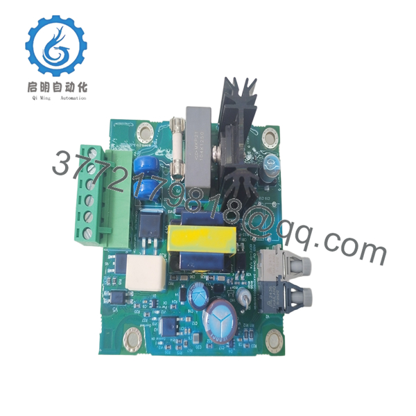
The ABB BDFC-01C functions as a dynamic braking control and interface board within large-scale ACS800 variable frequency drive cabinets. It precisely handles energy discharge cycles through heavy-duty braking resistors during motor deceleration sequences, protecting the primary DC bus link from overvoltage conditions. This module acts as a critical link between the core drive control system and high-voltage power components across mining, marine propulsion, and heavy manufacturing installations.
Procuring this module as a Brand New Surplus unit offers an excellent balance between cost efficiency and total asset reliability. Because the BDFC-01C serves a high-criticality insurance role on the factory floor, choosing unverified secondhand equipment exposes your operation to major risks. Used or refurbished components frequently hide degraded electrolytic capacitors and invisible thermal stress beneath a clean exterior. Investing in verified new surplus stock helps engineers lock down original OEM performance metrics at a lower cost than standard factory list pricing, while securing a predictable 10-15 year hardware lifespan.
5. Installation & Configuration Guide
Stage 1: Pre-Installation (Prep & Safety)
- Execute absolute lock-out/tag-out (LOTO) protocols on the incoming AC line power feeding the entire drive panel.
- Wait at least 15-20 minutes for the internal intermediate DC bus capacitors to discharge safely below 50 V DC. Verify zero voltage at the bus test points using a certified digital multimeter.
- Put on a properly grounded anti-static wrist strap before opening the protective electrostatic discharge (ESD) packaging.
- Document the exact terminal routing, fiber optic locations, and any factory jumper pin positions on the existing board with high-resolution photographs.
Stage 2: Removal
- Unplug the fiber optic cable assemblies carefully by holding the outer connector housings—never pull directly on the delicate optical strands.
- Disconnect the auxiliary 24 V power connectors and logic signaling terminal strips.
- Undo the retaining hardware holding the circuit card to the drive chassis frame.
- Slide the module straight out along its mounting path to prevent scratching the trace surfaces or bending any rear connector pins.
Stage 3: Installation (Clone & Seat)
- Compare the new BDFC-01C side-by-side with the removed component to ensure identical layout configuration.
- Transfer any specific jumper wire arrangements or mechanical hardware standoffs to match the original setup.
- Position the card onto the drive chassis alignment rails, pressing firmly until the board seats fully into position.
- Secure all mechanical fasteners and reconnect the low-voltage control terminal blocks and fiber optic leads into their designated ports.
Stage 4: Power-On & Testing
- Conduct a quick continuity test across the 24 V DC power lines to rule out any accidental direct grounding paths.
- Re-energize the drive control voltage circuit while keeping the primary high-voltage main lines disconnected.
- Observe the integrated LED indicators to verify the board passes its initialization routine without turning on an error light.
- Apply main line power, execute a low-speed dry run cycle, and monitor the drive diagnostics interface to confirm successful handshake telemetry with the dynamic braking subsystem.

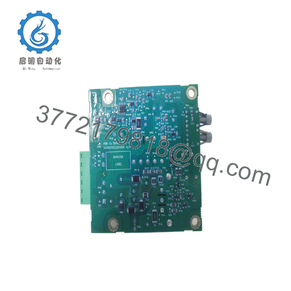
- BDFC-01C
- BDFC-01C
6. Firmware/Software Versions & Upgrade Notes
The BDFC-01C operates as a hardware-driven signaling interface that depends on accurate synchronization with the main drive processor firmware (such as the main AM33 or RMIO system application programs). This module requires the drive firmware version to remain fully compatible with standard factory revisions to prevent unexpected communication dropouts or fault conditions.
⚠️ Critical Risk Warning: Modifying firmware code settings or changing parameter versions during an emergency hardware swap can alter how the drive identifies individual I/O channels. Unplanned firmware mismatches regularly cause serious control loop timing errors or trigger false overvoltage warnings. Keep the drive parameters set exactly to their proven baseline levels unless a formal upgrade package is required for system safety.
7. Frequently Asked Questions (FAQ)
Is this BDFC-01C unit a refurbished item or a clean pull?
This product is a guaranteed Brand New Surplus unit. It has never run in a live factory environment, has never undergone circuit repair work, and was not salvaged from a decommissioned drive panel. It ships in original OEM anti-static wrapping that is opened only for brief quality assurance testing.
Why is the price lower than standard OEM pricing but higher than used parts?
Our pricing directly reflects the strict quality verification processes needed to secure genuine, untracked new surplus stock from global channels. While second-hand alternatives look cheaper initially, they lack the necessary reliability for heavy machinery. This component gives you a complete 100% factory-level lifespan at a more balanced investment level.
Can I hot-swap this card while the inverter cabinet is energized?
No. Attempting to hot-swap this control board while power is applied will cause permanent electrical damage. The fiber optic links and low-voltage control lines interface directly with the sensitive logic processors of the drive. Always cut power and verify the DC bus is completely discharged before working on the hardware.
Does this interface module store parameter settings or drive application logic?
The BDFC-01C processes hardware-level interface signals rather than storing complex field application logic programs. All primary operational settings stay saved within the main drive control board memory. This makes physical swapping straightforward, provided all jumpers and wire configurations match the original module exactly.
What kind of warranty coverage comes with this new surplus module?
We back this new surplus component with a full 1 year warranty against defects. This coverage matches standard factory terms and provides far better security than the minimal 30-day guarantees common with refurbished parts.



