
 WhatsApp: +86 16626708626
 Email:
  Phone: +86 16626708626
Description
3. Key Technical Specifications
| Parameter | Specification / Value |
| Model / Type | CMA198 / CMA198/1A / CMA198 AE2 |
| Co-Brand / Developer | Stucke Elektronik GmbH / ABB |
| Nominal Current (I_n) | 1.0 A |
| Current Range Allocation | 1.2 to 3.5 \times I_n (Adjustable via onboard potentiometer -R1) |
| Time Delay Adjustment | 0.2 to 2.0 seconds (Adjustable via onboard potentiometer -R2) |
| Output Configuration | Dry relay contact outputs for trip circuit initiation |
| Max Output Rating | Max 48 V, 700 mA |
| Terminal Connections | Multi-point heavy-duty screw terminal block at base |
| Physical Enclosure | Integrated DIN-rail or surface mount black housing with transparent upper adjustment panel |
4. Product Introduction & Supply Chain Strategy
The ABB Stucke CMA198 is a specialized, rugged overcurrent and short-circuit protection relay module widely used in marine power generation, offshore platforms, and heavy industrial distribution networks. Developed in cooperation with Stucke Elektronik, the CMA198 keeps continuous watch over phase current profiles (I_1, I_2, I_3). When current spikes past safe setpoints, the module triggers downstream breaker trip coils within fractions of a second. This targeted isolation prevents massive thermal destruction in generators and motors.
Because the CMA198 serves as a primary protective barrier, an unaddressed fault card or an unexpected failure will instantly drop your generator safety logic loops, forcing an emergency system shutdown. Opting for certified New Surplus inventory guarantees that you secure an original factory-spec component, completely bypassing the risks of long procurement lead times or inflated emergency factory costs. Refurbished protection modules introduce significant operational danger; worn-out internal capacitors or degraded relay contacts can cause drift in trip timing calibrations or fail to open under true short-circuit events. Sourcing factory-sealed surplus components provides the strict timing accuracy, precise setpoint control, and decades-long lifespan needed for critical safety loops.
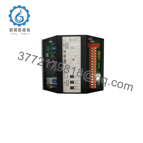
- CMA198
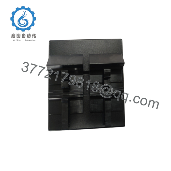
- CMA198
5. Installation & Calibration Guide
Stage 1: Pre-Installation (Prep & Safety)
- Isolate the main circuit breaker trip circuits and turn off all auxiliary power feeding the protection panel enclosure.
- Short-circuit the secondary loops of all connected Current Transformers (CTs) ahead of the module to prevent dangerously high voltage build-up.
- Verify that the ambient cabinet layout provides clean, vibration-free mounting conditions.
- Record the specific short-circuit setpoint (I_{range}) and time delay seconds configured on the unit being replaced.
Stage 2: Removal
- Double-check that no current is flowing through the measurement loops using a clamp meter.
- Carefully loosen the screw terminals on the front block and label each wire matching its exact channel placement (1 through 16).
- Release the physical DIN rail bracket spring or loosen the rear face framework mounting screws.
- Pull the module straight off the rail, making sure not to snag or strain adjacent wiring trunks.
Stage 3: Installation & Calibration
- Snap the new surplus CMA198 module securely onto the targeted section of the DIN rail track.
- Reconnect all sensor and power lines to their designated terminals, ensuring every screw is tightened down firmly to avoid high resistance points.
- Calibrate Setpoints: Locate the adjustment potentiometers on the exposed upper circuit face. Use an insulated calibration tool to match your system specifications:
- Adjust -R1 to select your precise Short-Circuit Setpoint multiplier (1.2 to 3.5 \times I_n).
- Adjust -R2 to set the required Short-Circuit Time Delay delay duration (0.2 to 2.0 s).
Stage 4: Power-On & Loop Commissioning
- Safely open the external current transformer secondary blocks to bring sensor lines back into an active monitoring state.
- Re-energize the auxiliary control circuit power and confirm that internal diagnostic components initialize smoothly.
- Conduct a secondary current injection test using a secondary relay test set to verify the absolute accuracy of the trip thresholds and timing loops.
- Verify that the clean dry contact trip signals successfully command the designated breaker open during test trip simulations.
6. Circuit Pinout Reference
To assist with physical wiring validation and loop tracking during maintenance checks, review the standardized front-panel terminal map:
- Terminals 1 & 2: Current input phase 1 (I_1) monitoring loop.
- Terminals 3 & 4: Current input phase 2 (I_2) monitoring loop.
- Terminals 5 & 6: Current input phase 3 (I_3) monitoring loop.
- Terminal 7: Chassis shield ground link point.
- Terminals 8 & 9: Auxiliary operating power supply inputs.
- Terminals 10 through 14: Internal relay trip signaling circuit array.
- Terminals 15 & 16: Auxiliary external monitoring connections (Max 48 V, 700 mA).
7. Frequently Asked Questions (FAQ)
What specific condition describes this CMA198 inventory?
This module is supplied exclusively as a certified Brand New Surplus asset. It remains inside its original factory-sealed protective anti-static packaging, has never been deployed in active service, and features original factory components with zero circuit modifications.
Why is using a refurbished module risky for an overcurrent protection loop?
Protection relays rely on high-precision timing components and healthy solid-state isolation paths. Refurbished parts can hide internal component fatigue caused by years of high operating temperatures. This fatigue can cause trip setpoints to drift or lead to complete relay failures during a short-circuit, risking severe damage to your generators and downstream equipment.
Can the CMA198 be calibrated directly on-site, or does it require pre-shipment software configurations?
The CMA198 features reliable analog hardware calibration. You adjust all short-circuit multipliers and time delay curves directly on the module using two onboard potentiometers (-R1 and -R2). This makes on-site tuning fast and straightforward without needing specialized software tools.
What is the purpose of short-circuiting the CT lines before replacing this card?
⚠️ High-Voltage Safety Hazard: Opening the secondary loop of an active current transformer (CT) generates dangerously high voltages across the open terminals. This can cause insulation breakdown, destroy equipment, and pose a severe shock hazard to technicians. Always short-circuit the CT secondary paths before disconnecting the measurement wires on terminals 1 through 6.
Does the module carry a replacement warranty?
Yes. Every new surplus CMA198 module includes a full 1 year replacement warranty. This gives your engineering team the same reliable warranty window as a new factory order, avoiding the short coverage periods typical of standard used components.



