
 WhatsApp: +86 16626708626
 Email:
  Phone: +86 16626708626
Description
3. Key Technical Specifications
| Parameter | Value |
|---|---|
| Manufacturer | ABB |
| Model | cRBX01 |
| Product Family | ABB Ability™ Symphony® Plus |
| Product Type | Fiber Optic Remote Bus Extender |
| Communication Protocol | HN800 |
| Communication Type | Fiber Optic Repeater |
| Transmission Speed | 4 Mbps |
| Maximum Fiber Distance | 3 km using 62.5/125 μm multimode fiber |
| Maximum Devices per Link | 60 HN800 I/O or communication modules |
| Fiber Connector | 2 × ST connectors |
| Diagnostics Port | Mini USB |
| Line Redundancy | Supported |
| Module Redundancy | No |
| Hot Swap | Supported |
| Mounting | RMU610 (Horizontal) or VMU610 (Vertical) |
| Operating Voltage | 24 V DC |
| Weight | Approximately 650 g (with base) |
| Operating Environment | Industrial Control Cabinets |
| Compliance | RoHS, WEEE |
4. Product Introduction
The ABB cRBX01 is a compact fiber optic remote bus extender for ABB Ability™ Symphony® Plus SD Series and HR Series controllers. It transparently extends the HN800 remote I/O bus over multimode fiber without requiring additional configuration, making it suitable for distributed process control applications where remote I/O cabinets are located hundreds or thousands of meters from the controller.
In field installations, the cRBX01 is commonly deployed in power generation, water treatment, oil and gas, and large industrial facilities where electrical isolation and long communication distances are required. It can also extend the CW800 communication bus for peer-to-peer communication between SD Series HPC800 controllers.
5. Installation & Configuration Guide
Stage 1 – Pre-Installation Preparation (10 Minutes)
⚠️ Safety First
- Notify operations of the planned maintenance.
- Place the control system in a safe operating condition.
- Lock out and tag out cabinet power.
- Wait at least five minutes before handling communication modules.
Required Tools
- Grounded ESD wrist strap
- Phillips screwdriver
- Fluke 115 digital multimeter
- Fiber optic cleaning kit
- Fiber inspection microscope
- Smartphone for documentation
Data Backup
Before replacing the module:
- Record controller configuration.
- Document the HN800 network layout.
- Photograph all fiber connections.
- Label transmit and receive fibers.
- Record controller firmware revision.
Stage 2 – Removing the Existing Module (10 Minutes)
- Disconnect cabinet power.
- Disconnect fiber optic cables carefully.
- Install dust caps immediately on all fiber connectors.
- Release the locking mechanism.
- Remove the module straight from the mounting base.
⚠️ Never bend multimode fiber below the specified minimum bend radius.
Inspect:
- ST fiber connectors
- Fiber end faces
- Mounting base
- Power terminals
Keep the original module until communication has been fully restored.
Stage 3 – Installing the New Module (10 Minutes)
- Wear an ESD wrist strap.
- Verify the replacement is an ABB cRBX01.
- Install the module into the RMU610 or VMU610 mounting base.
- Connect power.
- Clean and reconnect the optical fibers.
Configuration Check
The cRBX01 normally requires no software configuration, but verify:
- Fiber TX/RX orientation
- HN800 topology
- Controller redundancy configuration
- Remote cabinet addressing
Self-Check:
- ✅ Fiber connectors clean
- ✅ Module fully seated
- ✅ Power connected
- ✅ Optical link established
Stage 4 – Power-On & Testing (15 Minutes)
Pre-Power Inspection
- Verify 24 V DC supply.
- Confirm fiber routing.
- Check cabinet grounding.
Startup Procedure
- Energize the communication cabinet.
- Observe module status LEDs.
- Verify optical link establishment.
- Confirm HN800 communication.
- Check all remote I/O stations.
- Monitor controller diagnostics for communication alarms.
⚠️ Troubleshooting
No communication
- Verify transmit and receive fibers are not reversed.
- Clean all optical connectors.
- Measure optical attenuation if necessary.
Communication intermittent
- Inspect fiber routing for excessive bending.
- Verify multimode fiber meets ABB specifications.
Redundant path unavailable
- Check the secondary optical path and redundant controller configuration.
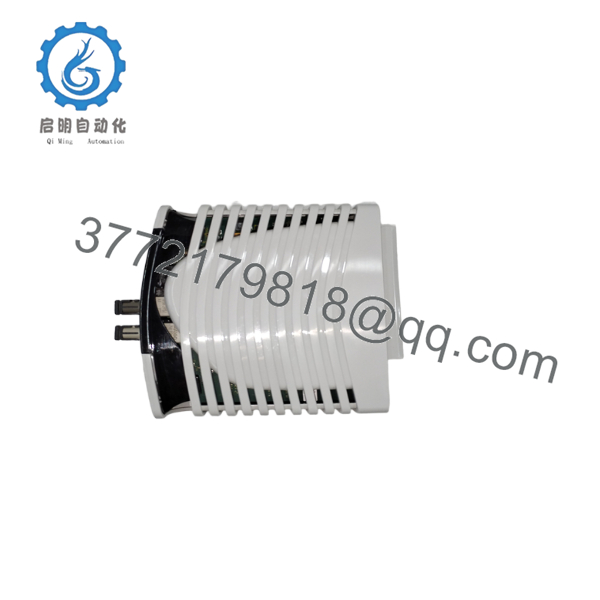
- cRBX01
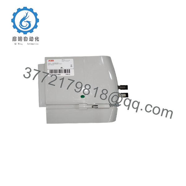
- cRBX01
6. Frequently Asked Questions (FAQ)
Q1. Does the cRBX01 require configuration after installation?
No. One advantage of the cRBX01 is that it operates transparently on the HN800 bus. In most installations, no module configuration is required. Communication parameters remain managed by the Symphony Plus controller.
Q2. What is the maximum communication distance?
Using ABB-recommended 62.5/125 μm multimode fiber, each remote HN800 link can extend up to 3 km. Fiber quality, connector cleanliness, and installation practices directly affect achievable distance.
Q3. Can the cRBX01 be hot-swapped?
Yes. The hardware supports hot swapping, but in a live production environment you should still follow your site’s maintenance procedures and evaluate the operational impact before replacing a communication module.
Q4. What is the most common installation mistake?
The mistake I see most often is contaminated fiber connectors. Even a connector that looks clean can introduce enough optical loss to cause intermittent communication. Always inspect and clean both ends before reconnecting.
Q5. Does the cRBX01 support redundant communication?
Yes. It supports redundant HN800 communication links, improving availability for distributed control systems. Module redundancy itself is not provided, but line redundancy is supported.
Q6. How many remote devices can one fiber link support?
Each remote HN800 link supports up to 60 SD Series I/O modules or communication modules without changing the communication architecture.
Q7. What should I verify before ordering a replacement?
Confirm:
- Exact model: ABB cRBX01
- Mounting orientation (RMU610 or VMU610)
- Fiber connector type (ST)
- Controller family (SD Series or HR Series)
- Existing HN800 network topology
Taking ten minutes to document the existing fiber routing and cabinet layout before removal can prevent hours of troubleshooting during commissioning.



