
 WhatsApp: +86 16626708626
 Email:
  Phone: +86 16626708626
Description
3. Key Technical Specifications
| Parameter | Value |
|---|---|
| Manufacturer | ABB |
| Model | DC532 |
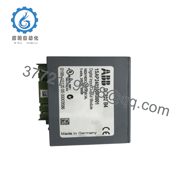
| Product ID | 1SAP240100R0001 |
| Product Family | AC500 S500 I/O |
| Product Type | Digital Input/Output Module |
| Digital Inputs | 16 × 24 V DC |
| Configurable Digital I/O | 16 × 24 V DC |
| Output Current | 0.5 A per configurable output |
| Wiring Method | 1-wire |
| Maximum Counter Frequency | 50 kHz |
| Module Isolation | Galvanically isolated |
| Supply Voltage | 24 V DC |
| Mounting | DIN Rail |
| Status Indication | Channel LEDs, power LED, diagnostic LEDs |
| Operating Temperature | 0 °C to +60 °C |
| Storage Temperature | -40 °C to +70 °C |
| Weight | Approximately 0.11 kg |
The module also includes grouped channel diagnostics, fast counter capability, and an XC variant for harsh environmental conditions.
4. Product Introduction
The ABB DC532 is an S500 digital I/O module designed for the AC500 PLC platform. It combines sixteen 24 V DC digital inputs with sixteen configurable digital input/output channels, allowing one module to handle both monitoring and control tasks within machine automation and process applications.
In field installations, the DC532 is commonly used where cabinet space is limited and mixed digital signals must be managed efficiently. Module-level galvanic isolation improves electrical noise immunity, while integrated diagnostics simplify fault localization during commissioning and maintenance. Verify CPU firmware compatibility before installation, particularly when upgrading older AC500 systems.
5. Installation & Configuration Guide
Stage 1 – Pre-Installation Preparation (10 Minutes)
⚠️ Safety First
- Notify operations before beginning maintenance.
- Place the machine in a safe operating state.
- Lock out and tag out the 24 V DC control supply.
- Wait at least five minutes before removing any I/O modules.
Required Tools
- Grounded ESD wrist strap
- PH1 screwdriver
- Fluke 115 digital multimeter
- Wire identification labels
- Smartphone for wiring documentation
Data Backup
Before removing the module:
- Save the AC500 PLC project.
- Record I/O addressing.
- Photograph terminal wiring.
- Record CPU firmware revision.
- Document any application-specific parameter settings.
Stage 2 – Removing the Existing Module (10 Minutes)
- Remove cabinet power.
- Label all field wiring.
- Disconnect the terminal unit carefully.
- Release the module locking mechanism.
- Pull the module straight from the S500 backplane.
⚠️ Do not force the module sideways. Bent bus connectors can damage adjacent I/O modules.
Inspect:
- DIN rail
- Terminal unit
- Bus connector
- Wiring condition
Keep the original module available until commissioning is complete.
Stage 3 – Installing the New Module (10 Minutes)
- Wear an ESD wrist strap.
- Confirm the replacement is ABB DC532 (1SAP240100R0001).
- Install the module firmly onto the S500 bus.
- Reinstall the terminal unit.
- Restore field wiring.
Configuration Check
Verify:
- Hardware configuration matches the PLC project.
- Channel assignments are correct.
- Output channels are configured correctly.
- CPU firmware supports the installed device index.
Self-Checklist
- ✅ Correct module installed
- ✅ Terminal block secured
- ✅ Wiring verified
- ✅ PLC configuration updated
Stage 4 – Power-On & Testing (15 Minutes)
Pre-Power Inspection
- Verify 24 V DC polarity.
- Measure for short circuits.
- Confirm protective grounding.
Startup Procedure
- Energize the PLC rack.
- Verify the green UP LED.
- Confirm no module error LEDs are active.
- Check all input status LEDs.
- Test each configurable output.
- Verify communication with the AC500 CPU.
⚠️ Troubleshooting Notes
Red CH-ERR LEDs
- Check output overloads or short circuits.
- Verify field wiring.
Module Error LED
- Confirm the PLC hardware configuration.
- Verify firmware compatibility.
Input not detected
- Measure the 24 V input signal.
- Confirm common reference wiring.
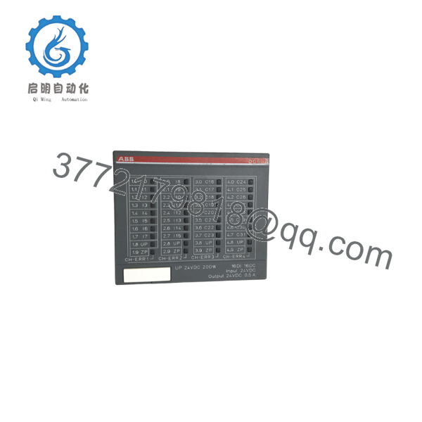
The DC532 provides individual channel LEDs, a process power indicator, and grouped channel error LEDs to simplify diagnostics during commissioning.

- DC532
- DC532
6. Frequently Asked Questions (FAQ)
Q1. Can the DC532 be hot-swapped?
No. Although the S500 platform simplifies module replacement, ABB recommends removing control power before replacing I/O modules to prevent configuration errors or backplane damage.
Q2. What signals does the DC532 support?
The module provides 16 dedicated 24 V DC digital inputs and 16 configurable digital input/output channels rated at 24 V DC and 0.5 A.
Q3. Is the DC532 compatible with every AC500 CPU?
Most current AC500 CPUs support the DC532, but compatibility depends on the CPU firmware and the I/O module device index. I’ve seen commissioning delayed because a replacement module required a newer firmware revision than the controller was running. Check the firmware before scheduling downtime.
Q4. What is the most common installation mistake?
The mistake I encounter most often is reconnecting field wiring without documenting the original terminal layout. A five-minute photo session before removal can eliminate hours of troubleshooting after startup.
Q5. Does the module provide diagnostics?
Yes. The DC532 includes dedicated LEDs for each input and configurable I/O channel, a process power indicator, grouped channel error LEDs, and a module error LED to assist with fault diagnosis.
Q6. Is there a version for harsh environments?
Yes. ABB offers the DC532-XC, which is designed for extended environmental conditions while maintaining the same functional characteristics as the standard module.
Q7. What should I verify before ordering a replacement?
Confirm:
- Exact part number (1SAP240100R0001)
- Standard or XC version
- CPU firmware compatibility
- Existing S500 hardware configuration
- Required I/O count and output current
One final recommendation from field experience: always compare the PLC hardware configuration with the physical rack before applying power. A mismatched hardware configuration can generate module faults even when the wiring is correct.



