
 WhatsApp: +86 16626708626
 Email:
  Phone: +86 16626708626
Description
3. Key Technical Specifications
| Parameter | Value |
|---|---|
| Manufacturer | ABB |
| Model | INICT13A |
| Product Type | Infi-Net to Computer Transfer Module |
| Product Family | Bailey INFI 90 OPEN / Symphony Harmony |
| Primary Function | Interface between INFI-Net and host computer systems |
| Supply Voltage | 5 VDC |
| Current Consumption | 2 A |
| Installation | Harmony Rack / INFI 90 module mounting unit |
| Communication Network | INFI-Net |
| Diagnostics | LED status indicators and system diagnostics |
| Typical Applications | DCS communication gateway, engineering workstation interface, supervisory computer connection |
| Weight | Approximately 0.36–0.50 kg (revision dependent) |
4. Product Introduction
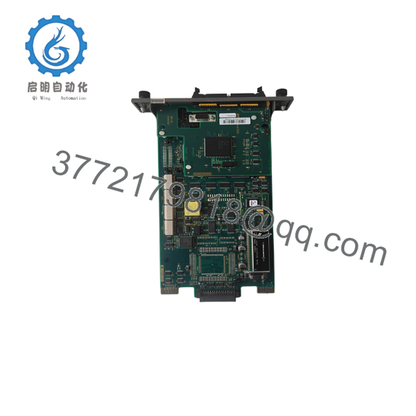
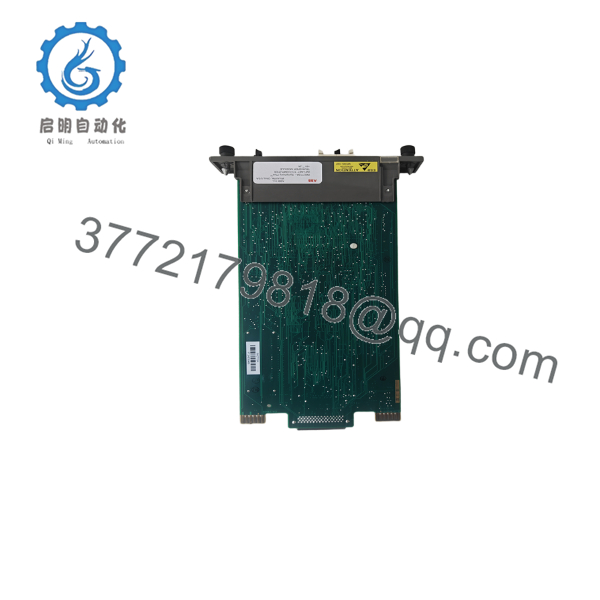
The ABB INICT13A is an Infi-Net to Computer Transfer (ICT) Module developed for the Bailey INFI 90 OPEN and Symphony Harmony distributed control systems. It provides the communication bridge between the INFI-Net control network and supervisory computers, engineering workstations, or operator interfaces, enabling process data exchange, configuration downloads, diagnostics, and system monitoring.
The INICT13A was introduced as the successor to earlier communication modules such as the INICT03A. During system modernization, ABB recommends the INICT13A as the evolution path for legacy ICT modules. Unlike earlier architectures that required an MPI module, the INICT13A integrates the required functionality, simplifying network design in many installations.

- INICT13A
- INICT13A
5. Installation & Configuration Guide
Stage 1 – Pre-Installation Preparation (10–15 minutes)
⚠️ Safety First
- Notify operations before taking the communication node offline.
- Apply Lock-Out/Tag-Out procedures.
- Power down the communication rack.
- Wait at least 5 minutes before removing modules.
- Wear a grounded ESD wrist strap.
Required Tools
- Phillips screwdriver
- Digital multimeter
- ESD wrist strap
- Engineering workstation
- Camera for documenting cable routing
- Network documentation
Before Removal
- Back up the INFI 90 configuration database.
- Record node addresses.
- Document communication parameters.
- Photograph all communication cable connections.
Stage 2 – Removing the Existing Module
- Disconnect all communication cables.
- Label every connector.
- Release the retaining clips.
- Pull the module straight from the rack.
- Inspect the backplane connector for bent pins or contamination.
⚠️ Keep the original module available until all network communications have been verified.
Stage 3 – Installing the Replacement Module
- Confirm the replacement module is INICT13A.
- Verify the hardware revision matches the installed system.
- Insert the module fully into the rack.
- Secure the locking mechanism.
- Reconnect communication cables.
- Verify switch settings before applying power.
Installation Checklist
- ✔ Correct module installed
- ✔ Node configuration verified
- ✔ Communication cables secured
- ✔ Module fully seated
- ✔ Grounding confirmed
Stage 4 – Power-On & Commissioning
- Restore rack power.
- Observe the module LED sequence.
- Verify communication with the INFI-Net.
- Confirm engineering workstation connectivity.
- Test data transfer between controllers and supervisory computers.
- Review diagnostic messages for communication errors.
⚠️ Troubleshooting
No communication with the host computer
- Verify node addressing.
- Inspect INFI-Net cabling.
- Confirm communication configuration.
Module remains offline
- Verify the 5 VDC backplane supply.
- Check rack connector seating.
- Confirm hardware compatibility.
Intermittent network faults
- Inspect cable shielding.
- Verify network termination.
- Confirm switch settings and firmware compatibility.
Field Experience: One common commissioning issue involves incorrect SW4 DIP switch settings. ABB documentation notes that SW4 poles 6, 7, and 8 must remain open when using the SCSI interface. Verifying these settings before startup can prevent unnecessary communication troubleshooting.
6. Frequently Asked Questions (FAQ)
Q1. What is the primary function of the INICT13A?
The INICT13A transfers data between the INFI-Net control network and supervisory computer systems, allowing engineering workstations, operator stations, and other host computers to exchange information with INFI 90 controllers.
Q2. Is the INICT13A a replacement for the INICT03A?
Yes. ABB’s documented evolution path identifies the INICT13A as the recommended replacement for the INICT03A. The newer design eliminates the need for a separate MPI module in many applications, reducing hardware complexity.
Q3. Can the INICT13A be hot-swapped?
Generally, no. Because it is a critical communication module, replacing it while the rack is energized can interrupt network communications and may damage the backplane. Unless your specific system documentation explicitly supports online replacement, isolate power before servicing.
Q4. What is the most common installation mistake?
The most frequent issue is assuming the replacement module’s communication settings match the original hardware. Before removing the existing module, record node addresses, switch positions, and communication parameters. Spending a few minutes documenting the configuration can save hours of troubleshooting.
Q5. Is the INICT13A still supported?
The INICT13A is considered a legacy Bailey INFI 90 communication module. Many industrial facilities continue to operate it successfully, but procurement is typically limited to new surplus inventory or professionally tested refurbished units. Verify the hardware revision before ordering.
Q6. What should I verify before commissioning?
Before placing the module into service, confirm:
- Correct hardware revision
- Backplane power integrity
- Node address configuration
- INFI-Net cable continuity
- DIP switch settings
- Communication diagnostics
- Successful data exchange with the engineering workstation
Completing these checks before returning the process to operation helps reduce commissioning delays and avoids unnecessary network troubleshooting.



