WhatsApp: +86 16626708626
 Email:
 Phone: +86 16626708626
Description
Core Product Summary
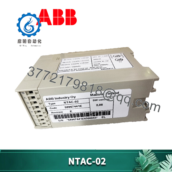
The ABB NTAC-02 is a pulse encoder interface module designed for the ACS 600 drive family. It provides the connection between a digital pulse encoder and the drive control system, enabling accurate speed and position feedback from the motor shaft.
The module mounts on a standard DIN rail inside or outside the drive and links to the drive via a fiber-optic DDCS connection. It supplies selectable 15 V or 24 V encoder power, accepts A/B/Z encoder signals up to 100 kHz, and is configured by DIP switches for node address. It is intended for ACS 600 Standard Application Program version 5.0 or later and compatible System and Crane application programs.
Key Technical Specifications
| Parameter | Value |
|---|---|
| Product type | Pulse encoder interface module |
| Drive family | ACS 600 |
| Max. signal frequency | 100 kHz |
| Speed feedback resolution | 0.00305 % (15 bits) |
| Encoder channels | A, B (90° electrical), Z (1 pulse/rev) |
| Encoder supply | Selectable 15 V or 24 V DC |
| Module supply | 24 V DC (max. 250 mA from NIOC or external) |
| Isolation | Encoder inputs isolated from power supply and earth |
| Enclosure | Plastic, IP20 |
| Dimensions (H × W × D) | 45 mm × 75 mm × 105 mm |
| Mounting | Standard DIN rail (inside or outside drive) |
| Drive connection | Fiber-optic (Hewlett-Packard Versatile Link) |
| Terminal blocks | Phoenix Contact MVBSTW 2,5/8-ST-5,08 |
| Conductor size | 0.5 to 2.5 mm² |
| Node address | DIP-switch selectable (default 16) |
Detailed Product Overview
The NTAC-02 serves as the dedicated pulse encoder interface for ACS 600 drives when precise speed or position feedback is required. It converts incremental encoder signals into data that the drive control board can use for closed-loop operation, improving control accuracy compared with sensorless methods.
The module connects to the drive over the DDCS fiber-optic link, typically to the NAMC or optional NDCO board. This optical connection provides electrical isolation and allows the module to be located either inside the drive cabinet or mounted externally on a DIN rail. Power for the module is taken from the NIOC board (maximum 250 mA) or an external 24 V DC supply; actual consumption depends on encoder type, pulse rate, cable length, and load.
Encoder power is generated on the module and can be set to 15 V or 24 V by jumper bridges supplied with the unit. The encoder interface accepts differential A, B, and Z signals. Channel B is expected 90 electrical degrees from Channel A; Channel Z provides one pulse per revolution for positioning reference. Maximum input frequency is 100 kHz. Logical thresholds are defined for both 15 V and 24 V encoder supplies, and the inputs are galvanically isolated from the module supply and earth.
Node address is set with seven DIP switches located inside the enclosure; the factory default is address 16. The package includes the module, three pairs of fiber-optic cables of different lengths, the two jumper bridges for voltage selection, a short DIN rail section, and the installation guide.
The NTAC-02 is not interchangeable with the earlier NTAC-01. Application software requirements and supply-voltage options differ, so the correct module must be selected according to the installed drive firmware and application program version.
NTAC-02
System Compatibility & Integration Requirements
| Item / Dependency | Verified Compatibility or Requirement | Practical Note |
|---|---|---|
| Drive family | ACS 600 | Required platform |
| Application programs | Standard V5.0 or later; System V4.2 or later; Crane V5.0 or later; Application Program Template (all versions) | Confirm firmware version before installation |
| Drive connection | Fiber-optic DDCS link to NAMC or NDCO board | Specific channel/terminal assignments depend on application program |
| Module power | 24 V DC from NIOC (max. 250 mA) or external supply | Check total current when encoder load is high |
| Encoder interface | Incremental A/B/Z signals, shielded twisted pair | Recommended encoder types include Leine & Linde 18690010 or Hübner POG 10 (or equivalent) |
| Node address | DIP-switch selectable | Default 16; must be unique on the DDCS link |
| Interchangeability | Not interchangeable with NTAC-01 | Different encoder supply voltages and software compatibility |
Dimensions, Mounting & Connection Notes
- Dimensions: 45 mm × 75 mm × 105 mm (plastic enclosure).
- Degree of protection: IP20.
- Mounting: Standard 35 mm DIN rail (DIN 50022). Can be installed inside the drive or externally. A short rail section is supplied.
- Drive connection: Hewlett-Packard Versatile Link fiber-optic transmitter/receiver. Three pairs of fiber cables (120 mm, 370 mm, 2000 mm) are included.
- Encoder and power terminals: Two Phoenix Contact MVBSTW 2,5/8-ST-5,08 screw terminal blocks. Conductor cross-section 0.5–2.5 mm².
- Encoder supply selection: Two jumper bridges provided for 15 V or 24 V.
- Current consumption: Module requires 24 V DC; maximum draw from NIOC is 250 mA. Additional external supply may be needed depending on encoder and cable parameters.
FAQ
What is the ABB NTAC-02?
It is a pulse encoder interface module that connects a digital pulse encoder to an ACS 600 drive for accurate speed and position feedback.
Which drives is the NTAC-02 compatible with?
It is designed for the ACS 600 family and requires Standard Application Program version 5.0 or later (or the listed System and Crane program versions).
How does the NTAC-02 connect to the drive?
It uses a fiber-optic DDCS link to the NAMC or NDCO board on the ACS 600.
What encoder signals does it accept?
Differential A, B, and Z channels with a maximum frequency of 100 kHz. Channel B is phase-shifted 90° electrically from Channel A; Channel Z provides one pulse per revolution.
What power does the module require?
24 V DC, taken from the NIOC board (maximum 250 mA) or an external supply. Encoder supply is selectable between 15 V and 24 V.
How is the node address set?
Seven DIP switches inside the enclosure set the node number. The factory default is 16.
Can the NTAC-02 replace an NTAC-01?
No. The modules are not interchangeable because of differences in encoder supply voltages and application-program compatibility.