WhatsApp: +86 16626708626
 Email:
 Phone: +86 16626708626
Description
Core Product Summary
ABB RTAC-01 is a pulse encoder interface module for connecting a digital incremental encoder to a compatible ACS800 drive. It receives motor-shaft speed or position feedback through A and B quadrature channels, with an additional Z reference channel for positioning applications. The module accepts differential or single-ended connections and supports a maximum encoder signal frequency of 200 kHz.
The RTAC-01 installs in SLOT 1 or SLOT 2 on the drive’s RMIO board, where a 38-pin connector carries power and signals between the module and drive. A jumper selects 15 or 24 V DC encoder power, with up to 5 W available without an external encoder supply. Selection depends on the encoder’s electrical output, pulse frequency, cable length, and power demand. The documented ACS800 Standard Application Program compatibility starts at ASXR7000; module activation and feedback settings are configured through drive parameters.
Key Technical Specifications
| Parameter | Specification |
|---|---|
| Manufacturer | ABB |
| Model | RTAC-01 |
| Product ID | 3ABD64610805 |
| Product type | Pulse encoder interface module |
| Primary function | Motor-shaft speed or position feedback |
| Documented drive-software compatibility | ACS800 Standard Application Program ASXR7000 or later |
| Encoder channels | A, B, and Z |
| Connection types | Differential or single-ended |
| Supported encoder output arrangements | Push-pull, open collector, and open emitter, with the applicable wiring |
| Maximum signal frequency | 200 kHz |
| Selectable encoder supply | 15 V DC ±10% or 24 V DC ±10% |
| Encoder supply capacity | 5 W maximum without an external supply; short-circuit protected |
| Signal thresholds at 15 V supply | Logic 1: >7.6 V; logic 0: <5 V |
| Signal thresholds at 24 V supply | Logic 1: >12.2 V; logic 0: <8 V |
| Speed-feedback resolution | 0.00305% — 15 bits |
| Speed-feedback accuracy | 50 ppm |
| Maximum cable length, differential push-pull | 300 m |
| Maximum cable length, single-ended push-pull | 200 m |
| Maximum cable length, open collector or open emitter | 100 m |
| Drive-side connection | 38-pin parallel bus connector |
| Field terminals | One 6-pole and one 8-pole non-detachable screw terminal block |
| Maximum terminal conductor size | 2.5 mm² |
| Degree of protection | IP20 |
| Diagnostic indicators | CHA, CHB, and WD/INIT |
The product ID identifies RTAC-01; electrical, feedback, cable, and installation specifications apply to the module.
Engineering Selection Highlights
- A/B/Z incremental feedback → matches quadrature encoders with an optional reference pulse; it is not an interface for an arbitrary absolute-encoder protocol.
- 200 kHz maximum input frequency → evaluate the encoder pulse count together with the maximum shaft speed, rather than selecting by supply voltage alone.
- Selectable 15 or 24 V encoder supply → match both the encoder’s supply requirement and its output signal levels to the selected configuration.
- 5 W internal encoder-power limit → an external supply is required when the encoder installation needs more power; cable loading and operating speed affect that assessment.
- Output-dependent cable limits → differential push-pull, single-ended push-pull, and open-output encoders have different permitted maximum cable lengths.
- RMIO SLOT 1 or SLOT 2 installation → the host drive must provide the appropriate option interface and support the selected installation through its firmware.
- Drive-parameter commissioning → installing the hardware does not activate or configure the feedback function automatically.
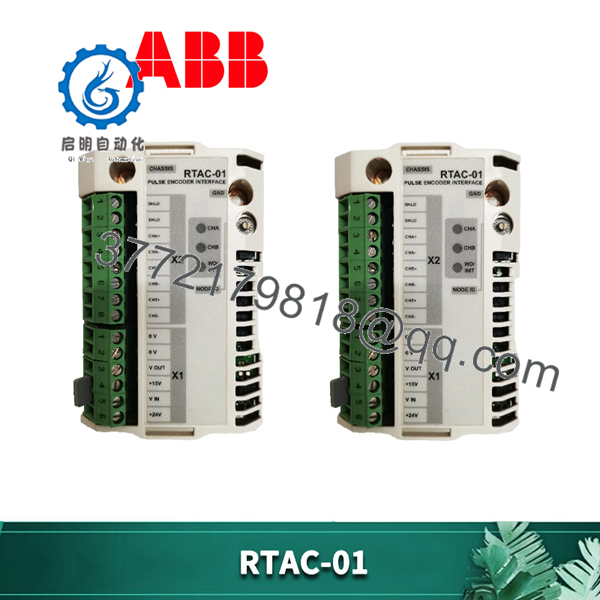
RTAC-01
System Compatibility & Integration Requirements
| Item / Dependency | Verified Compatibility or Requirement | Practical Note |
|---|---|---|
| Drive software | ACS800 Standard Application Program ASXR7000 or later | This statement is specific to the documented application program, not every ABB drive or firmware package. |
| Direct mounting | RMIO board SLOT 1 or SLOT 2 | Select the installation location supported by the drive’s firmware configuration. |
| Drive connection | 38-pin connector | Carries module power and drive communication when installed. |
| External mounting arrangement | AIMA-01 I/O Module Adapter | Provides an alternative arrangement through the supported drive communication configuration. |
| Encoder feedback | A/B quadrature; Z reference channel for positioning | A must lead B by 90 electrical degrees during forward rotation. |
| Encoder power | Jumper-selected 15 or 24 V DC, up to 5 W | Higher power demand requires an external supply. |
| External encoder supply | Remove the X1 voltage-selection jumper | The external-supply wiring arrangement differs from internally supplied operation. |
| Drive setup | Parameter groups 50 and 98 | Activation and encoder settings depend on the application firmware. |
| External-adapter addressing | Rotary switch positions 0–F represent node IDs 16–31 | The applicable drive firmware may require a particular node ID; the ACS800 Standard Control Program specifies node 16 for RTAC-DDCS. |
Hardware requirements and addressing are documented for RTAC-01; the specific RTAC-DDCS node requirement applies to the ACS800 Standard Control Program configuration.
Dimensions, Mounting & Connection Notes
Mounting and grounding
The RTAC-01 is retained in the RMIO option slot by plastic clips and two fixing screws. The screws also provide grounding connections for the module and cable shield, so correct screw installation is necessary for operation and EMC performance. The module has an IP20 protection rating; applicable ambient limits follow the host drive’s installation requirements.
Encoder cable and terminals
Use a 4 × (2+1) twisted-pair cable with individual pair shields and an overall shield. The specified cable-conductor cross-section is 0.5–1.0 mm²; the terminal blocks accept conductors up to 2.5 mm². Do not route the encoder cable parallel to motor or other power cables.
| Encoder Output Arrangement | Maximum Cable Length |
|---|---|
| Differential push-pull | 300 m |
| Single-ended push-pull | 200 m |
| Open collector or open emitter | 100 m |
These are output-dependent limits, not a single universal cable-length rating.
Shield termination depends on the encoder’s grounding arrangement. If the encoder is not isolated from the motor and earth, ground the cable shields at the RTAC module only. If the encoder is isolated from the motor and earth, connect the shields to the encoder housing as well.
Installation safety
Electrical installation and maintenance must be performed by qualified personnel with the drive safely isolated. After mains disconnection, observe the drive’s capacitor-discharge procedure and verify the absence of dangerous voltage; external control circuits can remain energized independently of the drive mains supply.
Detailed Product Overview
The RTAC-01 connects the electrical output of an incremental encoder to the feedback functions of a compatible drive. Its A and B inputs receive signals separated by 90 electrical degrees. During forward motor operation, the leading encoder output must connect to input A and the trailing output to input B. This phasing determines the sign of the measured feedback, so matching channel names alone is not sufficient if the encoder uses different marking conventions.
The Z channel serves a different purpose. It receives the once-per-revolution reference used in positioning applications and does not need to be connected solely to obtain speed feedback. Keeping these functions distinct helps avoid treating all three channels as mandatory for every installation.
Electrical compatibility requires attention to both supply and signal thresholds. The module offers jumper-selected 15 or 24 V DC encoder power, and its documented logic thresholds differ with that selection. The presence of differential inputs therefore does not establish compatibility with every differential encoder output. The encoder’s voltage levels and output circuit must match the RTAC-01 input arrangement.
Power demand is another installation-dependent condition. Up to 5 W is available to the encoder without an external supply, but encoder consumption is affected by shaft speed, pulses per revolution, cable length, and cable capacitance. When an external supply is required, the voltage-selection jumper must be removed and the external-power wiring arrangement used.
The maximum cable distance also depends on output type. Differential push-pull supports the longest documented run at 300 m, compared with 200 m for single-ended push-pull and 100 m for open collector or open emitter. These limits do not eliminate the need for the specified shielded twisted-pair cable, correct shield grounding, or separation from power wiring.
Commissioning finishes at the drive, not at the terminal block. The module is configured through drive parameters, including activation and encoder settings in groups 98 and 50. Firmware determines the available connection selections. For external-adapter arrangements, node addressing is an additional requirement; direct option-slot installation does not require the module’s node ID to be set.
Applications & System Role
The RTAC-01 adds incremental encoder feedback to a compatible drive-control architecture. A and B provide quadrature information for shaft speed and direction, while Z supplies a once-per-revolution reference for supported positioning functions. The module interfaces the encoder signals to the drive; it does not replace the encoder or independently perform the complete motion-control function.
Relevant technical-fit scenarios include a compatible ACS800 installation requiring measured shaft-speed feedback or a supported positioning application requiring an encoder reference pulse. Correct fit depends on the encoder output circuit, signal levels, pulse frequency, cable arrangement, and drive application program.
FAQ
What is ABB RTAC-01?
ABB RTAC-01 is a pulse encoder interface module for supplying motor-shaft speed or position feedback to a compatible drive. It accepts incremental encoder channels A, B, and Z.
Which ACS800 application software supports RTAC-01?
The documented compatibility is ACS800 Standard Application Program ASXR7000 or later. Other drive application programs require their own documented compatibility and configuration.
Does RTAC-01 support differential and single-ended encoders?
Yes. It supports differential and single-ended connections, with documented wiring for push-pull, open-collector, and open-emitter outputs. The encoder signal levels must meet the module’s input thresholds.
Can RTAC-01 power the encoder?
Yes. It supplies selectable 15 or 24 V DC, up to 5 W, without an external encoder supply. Higher power demand requires an external supply and removal of the voltage-selection jumper.
What is the maximum encoder input frequency?
The maximum signal frequency is 200 kHz. Encoder pulse count and maximum operating speed must be assessed against this limit.
Is the Z channel required for speed feedback?
No. The Z reference channel is needed for positioning applications that use the once-per-revolution reference, not for speed feedback alone.
How far can the encoder be installed from the module?
The maximum cable length is 300 m for differential push-pull, 200 m for single-ended push-pull, or 100 m for open-collector or open-emitter outputs. The specified cable construction and grounding requirements still apply.
What do the diagnostic LEDs indicate?
CHA and CHB indicate activity on encoder channels A and B. WD/INIT indicates module status and is illuminated while the drive configures the module at power-up.