
 WhatsApp: +86 16626708626
 Email:
  Phone: +86 16626708626
Description
Key Technical Specifications
| Parameter | AL81G Specification |
|---|---|
| Manufacturer | Acquisition Logic / UTEX |
| Model | AL81G |
| Product Type | High-speed A/D digitizer |
| Analog Channels | 1 |
| ADC Resolution | 8 bits |
| Maximum Sampling Rate | 1 GSamples/s |
| Available Sampling Rates | 1000, 500, 250, 100 MSamples/s |
| Analog Bandwidth | DC to 350 MHz |
| Input Impedance | 50 Ω |
| Input Ranges | 125 mV, 250 mV, 500 mV, 1 V peak-to-peak |
| Onboard Memory | 64 MSamples |
| Optional Memory | 256 MB |
| Host Interface | PCI, 32-bit, 33 MHz |
| PCI Transfer | Up to 133 MB/s burst |
| DMA | PCI bus-master DMA with scatter/gather support |
| Analog Connector | BNC |
| Trigger Connector | BNC |
| Trigger Sources | Signal threshold, encoder, software, external/internal trigger |
| Board Dimensions | 9.35 × 4.2 in. PCI board |
| Power | +5 V at 2.0 A; +3.3 V at 4.5 A; +12 V at 0.1 A; −12 V at 0.1 A |
| Operating Temperature | Not verified from the original specification located |
| Status | Obsolete |
The original specification identifies the AL81G as a single-channel, 1 GS/s, 8-bit A/D board with 64 MSamples of acquisition memory, a 50 Ω input, DC–350 MHz bandwidth, and a 32-bit/33 MHz PCI interface.
Important Identification Note
The AL81G is not a conventional PLC, DCS I/O module, or general-purpose controller. It is a specialized high-speed data-acquisition/digitizer board intended for waveform acquisition and test/inspection systems. The UTEX quick-start documentation also shows dedicated Ch A, Trig, Internal Trigger, and Encoder Trigger connections.
Do not substitute specifications from unrelated AL81G reseller pages. Several secondary listings incorrectly describe the board as a modern industrial controller or claim interfaces such as Ethernet, USB 3.0, and RS-485. Those claims are inconsistent with the original AL81G specification, which specifies a PCI bus and BNC signal connections.
Product Introduction
The Acquisition Logic is a single-channel high-speed A/D digitizer designed for capturing fast analog waveforms in legacy inspection, measurement, and test systems. Its 1 GS/s sampling rate, 8-bit conversion, 350 MHz analog bandwidth, 50 Ω input, and onboard acquisition memory make it suitable for applications where waveform timing and high-speed transient capture are more important than high channel density.
The most important procurement issue is the host interface. The uses a 32-bit, 33 MHz PCI bus, so physical PCI compatibility, legacy drivers, acquisition software, and the original host computer must all be considered. UTEX documentation identifies among its legacy Acquisition Logic digitizers supported by older Winspect/InspectionWare environments.
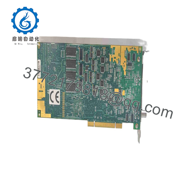
AL81G
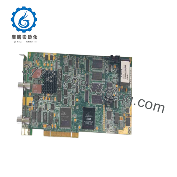
AL81G
Installation & Configuration Guide
Stage 1 — Pre-Installation Preparation
- Confirm the existing board identification. Check the model marking, PCB revision, serial number, memory configuration, and connector arrangement.
- Verify the host computer. The system must provide a compatible 32-bit, 33 MHz PCI slot; PCIe compatibility should not be assumed.
- Back up the existing acquisition software, drivers, configuration files, and working host image.
- Record the existing sampling rate, input range, trigger source, pre-trigger/post-trigger settings, and acquisition memory configuration.
- Disconnect power before opening the industrial PC or test chassis.
⚠️ Do not attempt to install the directly into a PCIe slot. The original specification calls for conventional PCI.
Stage 2 — Removing the Existing Board
- Shut down the acquisition system according to the equipment manufacturer’s procedure.
- Remove AC power from the host chassis.
- Label the analog and trigger cables before disconnecting them.
- Remove the PCI retaining screw or bracket hardware.
- Pull the existing board vertically from the PCI connector.
- Inspect the PCI slot and signal cables for contamination, mechanical damage, or bent contacts.
Stage 3 — Installing the
- Verify that the replacement board has the same hardware configuration as the installed .
- Wear appropriate ESD protection when handling the PCI board.
- Align the PCI edge connector carefully with the motherboard slot.
- Press the board evenly into the connector without excessive force.
- Secure the board to the chassis.
- Reconnect the BNC analog and trigger connections according to the original configuration.
- Restore the acquisition software and compatible driver environment.
Stage 4 — Power-On & Testing
- Restore power and check that the host computer recognizes the PCI device.
- Verify the installed Acquisition Logic driver before launching the acquisition application.
- Confirm the configured sampling rate and input range.
- Apply a known test signal through the 50 Ω analog input.
- Test the required trigger source and verify waveform capture.
- Check pre-trigger and post-trigger acquisition behavior.
- Confirm DMA transfers complete without dropped samples or acquisition errors.
- Compare the captured waveform against a known-good reference.
⚠️ Because the is obsolete, do not use a modern driver or PCIe replacement as a drop-in assumption. UTEX documentation specifically identifies legacy Acquisition Logic driver environments for systems.
FAQ
Is the a PLC or DCS I/O module?
No. The is a single-channel high-speed A/D digitizer. It is designed for analog waveform acquisition rather than conventional PLC/DCS control I/O.
What is the maximum sampling rate?
The maximum specified sampling rate is 1 GSamples/s, with selectable rates of 1000, 500, 250, and 100 MSamples/s.
What resolution does the use?
The A/D converter provides 8-bit resolution on its single analog channel.
What type of PCI interface does it require?
The requires a 32-bit, 33 MHz PCI interface and supports PCI bus-master operation and DMA transfers. It should not be treated as a PCIe card.
How much onboard memory does it have?
The standard configuration provides 64 MSamples of acquisition memory, with an optional 256 MB configuration documented in the original specification.
Is still a current product?
No. The archived manufacturer specification states that the product was obsolete as of August 2013. UTEX’s support site continues to retain documentation for the legacy , while its documentation also identifies newer AL81xGTe and AL83xGTe digitizers.
Can a newer digitizer replace the directly?
Not automatically. A replacement must be evaluated against the PCI/PCIe interface, driver environment, acquisition software, trigger timing, memory behavior, cabling, and data format. For a running inspection system, replacing the board without validating the complete acquisition chain can create compatibility problems even when the newer digitizer has higher nominal performance.



