
 WhatsApp: +86 16626708626
 Email:
  Phone: +86 16626708626
Description
3. Key Technical Specifications
| Parameter | Value |
|---|---|
| Display | 5½-digit, maximum reading 319999 |
| DC Voltage Range | 300 mV to 200 V |
| Min. DC Voltage Resolution | 0.1 µV |
| Resistance Range | 30 Ω to 30 MΩ (2-wire/4-wire) |
| Min. Resistance Resolution | 100 µΩ |
| Ripple Voltage Ranges | 30 mV, 300 mV, 3 V |
| Ripple Voltage Resolution | 10 µV |
| Max. Sampling Rate | 1000 cycles/s (BURST mode) |
| Sampling Modes | FREE / HOLD / BURST; FAST / MED / SLOW / LONG-IT |
| Data Memory | 10,000 readings |
| Interfaces | GPIB and RS-232C (standard, front-panel selectable) |
| Display Type | 7-segment fluorescent character tube with bargraph |
| Power Supply | AC 100/200 V |
| Open Terminal Voltage | Max. 8 V |
4. Product Introduction
The Advantest R6552T-R is a 5½-digit digital multimeter from the R6552 series designed for both system integration and bench-top use. It delivers high-resolution measurements of DC voltage, resistance, and specialized ripple voltage, with a maximum display of 319999 and sampling rates up to 1000 readings per second in BURST mode.
Engineers choose the R6552T-R when fast data acquisition, low-level sensitivity (0.1 µV DC, 100 µΩ resistance), and dual GPIB/RS-232 remote control are required. The instrument includes 10,000-point internal memory, LONG-IT averaging, and true multipoint system compatibility. As a discontinued model, remaining New Surplus units continue to serve legacy ATE racks and calibration stations where form-fit-function continuity is essential.
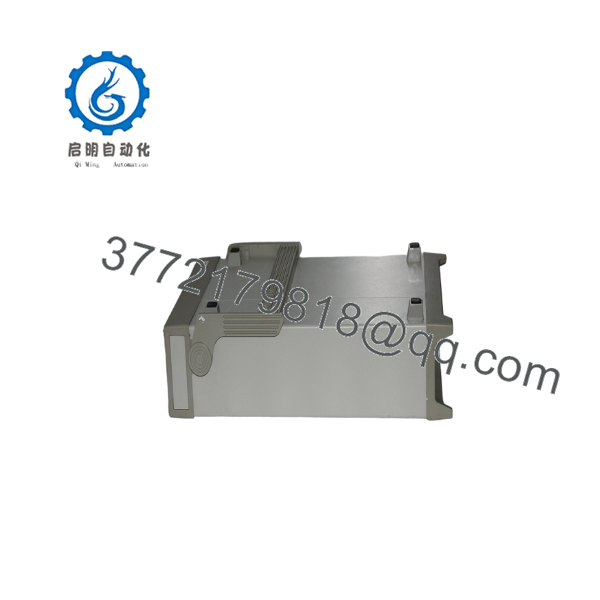
R6552T-R
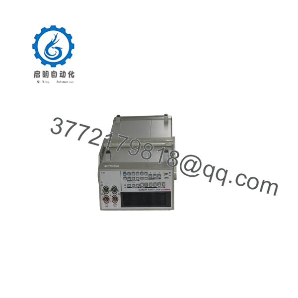
R6552T-R
5. Installation & Configuration Guide
Stage 1: Pre-Installation Preparation (≈5–10 min)
⚠️ Safety First: Disconnect power. Verify the AC line voltage selector matches the local supply (100 V or 200 V). Allow the instrument to warm up a minimum of 60 minutes for full accuracy after power-on.
Tools Required: ESD wrist strap, appropriate input cables (standard accessories include power cord and measurement leads), multimeter for continuity checks if needed, and documentation of existing GPIB address or RS-232 settings.
Data Backup: Record current GPIB address, RS-232 baud rate/parity, and any stored parameter sets from the front panel or remote controller.
Stage 2: Removing the Old Unit (≈5 min)
- Power down the instrument and disconnect the AC power cord.
- Label and disconnect all input test leads, GPIB cable, and RS-232 cable.
- If rack-mounted, release the mounting hardware and slide the unit out carefully.
- Inspect connectors for damage or contamination.
⚠️ Retain the old unit until the replacement has completed functional verification.
Stage 3: Installing the New Unit (≈10 min)
- Confirm the exact model marking “R6552T-R”. Wear an ESD strap while handling.
- Configuration Clone (Critical): Set the GPIB address or select RS-232 mode to match the previous installation. Replicate any custom LONG-IT or comparator settings from notes or photographs of the old front panel.
- Install the unit in the rack or on the bench. Secure mounting hardware if used.
- Reconnect the power cord, GPIB or RS-232 cable, and measurement leads.
Self-Checklist: [ ] Line voltage selector correct [ ] Interface mode and address match previous unit [ ] Cables secured [ ] ESD precautions observed.
Stage 4: Power-On & Testing (≈10–15 min)
Pre-Power Check: Verify no short exists on the input terminals and that the correct fuse is installed.
- Apply AC power. Observe the fluorescent display for normal boot and self-test.
- Allow 60 minutes warm-up for specified accuracy.
- Perform a shorted-input zero check and a known-source verification on DC voltage and resistance ranges.
- Confirm remote communication by querying the instrument over GPIB or RS-232.
- Test RIPPLE V function and BURST sampling if used in the application.
⚠️ Troubleshooting Note: If remote communication fails, confirm interface selection (GPIB vs. RS-232) on the front panel and cable integrity. Unstable low-level readings usually indicate insufficient warm-up or improper input lead connections. Solid error indications require checking the internal fuse and power-line voltage selector.
6. Frequently Asked Questions (FAQ)
Q: Can the R6552T-R be hot-swapped or left powered while changing cables?
No. Always remove AC power before connecting or disconnecting input leads or interface cables. The instrument is not designed for live input changes under all conditions.
Q: Is this model obsolete, and is the stock genuinely new?
Yes, the R6552 series has been discontinued by Advantest. Available units are New Original (new surplus) stock that has been verified functional. Quantities are limited; confirm current availability when ordering.
Q: What is the direct functional replacement if R6552T-R stock is exhausted?
Modern 5½-digit or 6½-digit system DMMs from Keysight, Keithley, or Advantest’s later product lines can replace the measurement functions. However, GPIB command set, physical footprint, and exact ripple-voltage behavior may differ. Verify software compatibility and rack space before substitution.
Q: Will I lose stored settings or data memory when I replace the unit?
Internal parameter backup and the 10,000-point data memory are retained only while the instrument remains powered or has valid battery-backed storage (if equipped). Always document critical settings before removal. After installation, re-enter GPIB address, sampling modes, and any comparator limits.
Q: Why is the price lower than the original Advantest list price?
These are New Surplus units from secondary-market inventory. They provide the same form, fit, and function as original production instruments and are fully tested, but they are no longer current-production factory items.
Q: Does the R6552T-R require special warm-up or calibration before use?
Yes. Full specified accuracy requires a minimum 60-minute warm-up. For critical applications, perform a verification against a traceable standard after installation. The instrument supports standard external calibration procedures.
Q: What interfaces are available and how are they selected?
Both GPIB (IEEE-488.2) and RS-232C are standard. Selection is made from the front panel. Only one interface is active at a time. Confirm the chosen interface matches the controlling computer or ATE system before relying on remote operation.



