
 WhatsApp: +86 16626708626
 Email:
  Phone: +86 16626708626
Description
Key Technical Specifications
| Parameter | Specification / Value |
|---|---|
| Manufacturer | AJINEXTEK (Ajin XtEk) |
| Part Number | AMW-MC12-DB96P |
| Core MCU | ARM Cortex-M4 Microcontroller |
| Product Category | Motion Control Terminal Board / Breakout Interface |
| System Compatibility | CAMC Motion Control Systems / PC-based Automation Platforms |
| Motion Command Outputs | Pulse / Direction, CW / CCW Differential Outputs |
| Main Connector | 96-Pin High-Density D-Sub / SCSI Connector Interface |
| I/O Logic Signals | Optically Isolated Inputs (Limit Switches, Home, In-Position, Alarm) & Relay/Transistor Outputs |
| Operating Voltage | 24 V DC External I/O Logic Power |
| Mounting Format | DIN-Rail / Baseplate Enclosure Mount |
| Operating Temperature | 0 to +50 °C (+32 to +122 °F) |
| Weight | Approx. 0.45 kg (0.99 lbs) |
Product Introduction & Supply Chain Strategy
The AJINEXTEK AMW-MC12-DB96P is an industrial-grade motion control breakout and terminal module engineered by Ajin XtEk, a leading supplier of PC-based motion control hardware widely used in semiconductor, OLED panel, and SMT manufacturing equipment. Built around an ARM Cortex-M4 processing engine, this module bridges host control boards to external servo drivers and field sensors via a high-density 96-pin connector setup.
Sourcing the AMW-MC12-DB96P as New Surplus provides automated manufacturing plants and OEM machinery builders with a reliable replacement path without facing long production lead times. Utilizing unused factory surplus guarantees clean contact pins, unaged onboard optocouplers, and structural integrity. Maintaining a spare AMW-MC12-DB96P in buffer stock protects cleanroom assembly tools and automated pick-and-place lines from costly emergency outages.
Installation & Configuration Guide
1
Pre-Installation & Safety Isolation
Isolate power supplies and wear ESD grounding protection
1.Pre-Installation & Safety Isolation:Isolate power supplies and wear ESD grounding protection.
- Lock out and tag out all 24 V DC field I/O power supplies and AC servo drive main power sources.
- Wear an ESD-grounded wrist strap connected to the chassis ground before handling the module.
- Verify that all interconnecting cable pinouts match AJINEXTEK hardware wiring diagrams.
2
DIN-Rail Mounting & Mechanical Fixation
2.DIN-Rail Mounting & Mechanical Fixation:
- Snap the AMW-MC12-DB96P onto a standard 35 mm DIN rail or secure it to the cabinet backplate using mounting screws.
- Ensure adequate ventilation space around the board to prevent thermal buildup within sealed control enclosures.
- Check that the grounding terminal is firmly bonded to the main machine frame earth.
3
Cable Hookup & Servo Drive Interfacing
3.Cable Hookup & Servo Drive Interfacing:
- Connect the primary 96-pin cable from the host controller card to the DB96P interface port and tighten the retaining screws.
- Wire the command signal outputs (Pulse/Dir), limit switch inputs (CW/CCW/Home), and drive status alarms to the terminal block interface.
- Connect the isolated +24 V DC field power supply to power external sensor inputs and output drivers.
4
Power-On Validation & Axis Commissioning
4.Power-On Validation & Axis Commissioning:
- Reapply power to the module and verify that the power LED illuminates steadily.
- Run diagnostic software (such as AJINEXTEK Motion Agent / EzSoftware) to test axis motion commands, encoder feedback signals, and safety limit trips.
- Execute low-speed jog commands on each axis to confirm motor rotation direction and signal integrity before running automated routines.
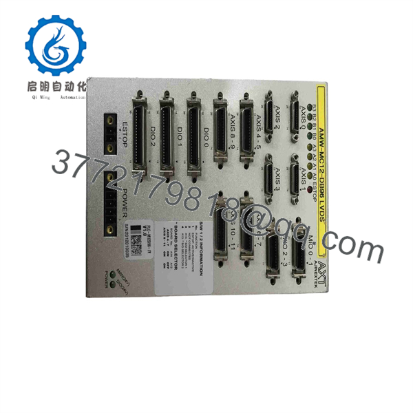
AMW-MC12-DB96P
Firmware/Software Versions & Upgrade Notes
- Software Compatibility: The AMW-MC12- interfaces with host-level software environments managed by AJINEXTEK API libraries (such as
EzMotion/CAMCdriver packages). Ensure host software drivers match the hardware family architecture. - Pinout Alignment: Always verify that the 96-pin cable pinout matches the drive allocation map. Incorrect wiring on differential pulse or 24 V logic pins can result in signal corruption or board damage.
- Noise Suppression: High-speed motion pulse lines are susceptible to electromagnetic interference (EMI). Ensure shielded twisted-pair cabling is used between the interface and motor drives.
Frequently Asked Questions (FAQ)
Is this AJINE unit genuine OEM and unused?
Yes, this unit is New Surplus (Original New). It is an authentic AJINEXTEK component sourced from canceled equipment integration projects or strategic spare reserves. It has never been deployed in active production lines.
Why choose New Surplus over refurbished motion cards?
Refurbished motion interface boards used in high-cycle semiconductor machinery often suffer from worn connector pins, degraded optocouplers, and thermal fatigue. In precise motion control applications, signal degradation can cause lost pulse steps, axis positioning errors, or unexpected emergency stops. New Surplus guarantees factory-fresh signal transceivers and 100% operational reliability.
Does this terminal module require dedicated driver software?
Yes. Communication with the host computer is managed through AJINEXTEK software development kits (SDKs) and DLL libraries, which allow C/C++, C#, or Visual Basic applications to execute motion commands and poll I/O channels.
Can this board control both servo and stepper drives?
Yes. supports standard differential pulse and direction output formats compatible with both AC servo systems and microstepping drive amplifiers.
What warranty is provided with this surplus component?
We back this unit with a 1-Year Comprehensive Replacement Warranty. E module undergoes physical inspection and continuity testing prior to shipment.



