
 WhatsApp: +86 16626708626
 Email:
  Phone: +86 16626708626
Description
3. Key Technical Specifications
- Application Platform: Alcatel-Lucent carrier-grade systems (transport / switching)
- Board Type: Plug-in PCB module (rack-mounted system)
- Backplane Interface: High-speed proprietary bus
- Signal Handling: Digital telecom signaling / data routing
- Power Supply: Via system backplane (typ. −48 V telecom standard)
- Operating Temperature: 0 to +55 °C (central office typical)
- Cooling Requirement: Forced air (chassis fan tray dependent)
- Connector Type: Backplane edge connector
- Revision: AM2 (hardware revision control)
- Compliance: Telecom central office standards (NEBS-style environments typical)
4. Product Introduction
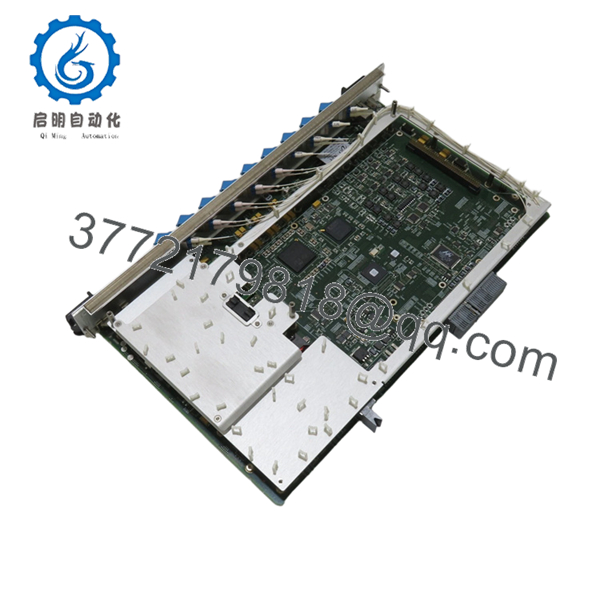
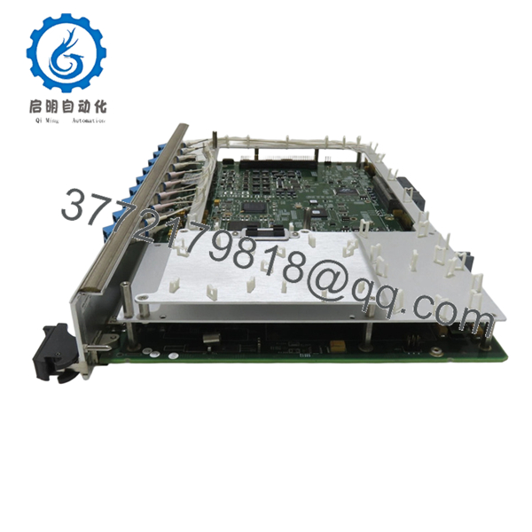
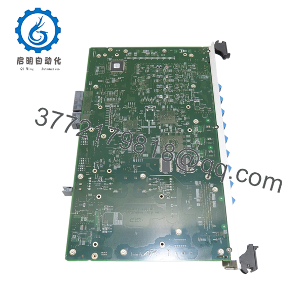
Alcatel-Lucent 8DG59236ABAA REV AM2 is a telecom-grade plug-in control or interface board used in carrier transport or switching systems. It installs into a chassis backplane and handles internal signaling, control-plane processing, or subsystem interfacing depending on system configuration.
In legacy Alcatel-Lucent deployments (pre-Nokia integration), boards like this are typically tied to specific shelves or subracks. Engineers keep them in service because replacing the entire platform is far more disruptive than maintaining spare boards. Hardware revision (REV AM2) matters — mixing revisions without validation can trigger compatibility issues.

- 8DG59236ABAA REV AM2
- 8DG59236ABAA REV AM2
- 8DG59236ABAA REV AM2
5. Installation & Configuration Guide
Stage 1: Pre-Installation Preparation (Estimated: 10–15 minutes)
- ⚠️ Safety First: Notify NOC, isolate affected service, power down the shelf if hot-swap is not explicitly supported. Telecom racks often run −48 V DC — treat it seriously.
- Tools Required: ESD wrist strap, flat/PH screwdriver, label tags, multimeter, smartphone.
- Data Backup: Record slot ID, board type, alarms, and system logs. Photograph slot layout and adjacent modules.
Stage 2: Removing the Old Module (Estimated: 5–10 minutes)
- Identify the exact slot location (these systems are slot-sensitive).
- Release ejector levers evenly.
- Pull straight out — do not twist; backplane pins are not forgiving.
- Inspect slot for dust, bent pins, or airflow obstruction.
- ⚠️ Note: Keep the original board nearby for revision comparison and fallback.
Stage 3: Installing the New Module (Estimated: 10 minutes)
- ESD protection ON — these boards are sensitive.
- Verify model and revision (REV AM2) matches system requirements.
- Insert board evenly into guide rails.
- Seat firmly using ejector levers until fully engaged.
- Self-Checklist:
- Model matches exactly
- Revision verified
- Board fully seated
- No obstruction in airflow path
Stage 4: Power-On & Testing (Estimated: 10–20 minutes)
- Pre-Power Check: Verify no short across power rails using a multimeter.
- Power-On Steps:
- Power up shelf or enable slot.
- Monitor LEDs (STATUS, ALARM indicators).
- Check system CLI/NMS for board recognition.
- Clear alarms and verify normal state.
- Run traffic or signaling test.
- ⚠️ Troubleshooting Note:
- Board not recognized → likely firmware mismatch or unsupported revision
- Persistent alarm → check slot compatibility or adjacent board dependency
- Intermittent faults → often airflow or backplane contact issue
6. Frequently Asked Questions (FAQ)
Q1: Can this module be hot-swapped?
Depends on the chassis. Some Alcatel-Lucent systems support hot-swap, others don’t. If you’re not 100% sure, power down the shelf. I’ve seen backplanes damaged by forcing a live insertion.
Q2: Is this model obsolete?
Yes. Most Alcatel-Lucent carrier hardware was absorbed into Nokia around 2016 . Support is limited, and availability depends on surplus stock.
Q3: What happens if I install a different revision (not AM2)?
❗ This is a common failure point.
Different revisions can have:
- Firmware expectations mismatch
- Different ASIC behavior
- Backplane timing differences
I’ve seen boards boot but throw persistent alarms because of revision mismatch.
Q4: Why isn’t the system recognizing the board?
Typical causes:
- Firmware mismatch at system level
- Wrong slot type
- Backplane connector wear
In older ALU systems, documentation is not always clear — double-check hardware compatibility lists.
Q5: Will I lose configuration when replacing this board?
Usually no. Configuration is stored at system level, not on the board. However, always back up — I’ve seen corrupted configs after hardware faults.
Q6: Why is pricing inconsistent across suppliers?
Because this is surplus telecom hardware. Supply comes from:
- Decommissioned networks
- Project overstock
- Carrier upgrades
Condition varies — always request test documentation.
Q7: What’s the biggest installation mistake?
❗ Forcing the board into the wrong slot.
These systems are not forgiving. I’ve seen engineers bend backplane pins — that turns a board swap into a full chassis replacement.
SOP Quality Transparency (Inspection & Testing Process)
1. Inbound Inspection & Traceability
- Verified against OEM packing lists and decommission records
- Serial number and labeling checked for authenticity
- Visual inspection under magnification (no corrosion, no rework marks)
- Connector edge inspection for wear or oxidation
2. Live Functional Testing
- Tested in a compatible Alcatel-Lucent rack (carrier-grade shelf)
- Power-on sequence verified (LED diagnostics)
- Backplane communication handshake confirmed
- Simulated traffic load test (continuous run >24 hours)
- Test report generated (available upon request)
3. Electrical Parameter Testing
- Insulation resistance test (>10 MΩ @ 500 V Megger)
- Ground continuity verified
- Power rail stability checked with Fluke 115 multimeter
4. Firmware & Configuration Verification
- Board revision documented (REV AM2)
- Firmware compatibility checked against system baseline
- Physical configuration recorded (if applicable)
5. Final QC & Packaging
- QC sign-off with date traceability
- Anti-static (ESD) sealed packaging
- Reinforced export-grade carton
- Shock protection with foam inserts
Test photos and videos are available upon request.
Technical Pitfall & Survival Guide
1. Firmware Revision Mismatch
❗ I’ve seen systems reject boards silently.
A tech swapped a similar board, and alarms persisted for two days — firmware baseline mismatch.
Avoidance: Always record system firmware before replacement.
2. Slot Misplacement
❗ Not all slots are equal.
Some boards only work in control slots vs. line slots.
Avoidance: Label and verify slot ID before removal.
3. Backplane Damage Risk
❗ This is expensive.
Bent pins = full chassis replacement in worst cases.
Avoidance: Insert straight, no force. If it doesn’t slide easily, stop.
4. Power Load Considerations
Telecom shelves share −48 V supply.
Adding boards increases load.
Avoidance: Check power margin — leave at least 20% headroom.
5. ESD Handling
❗ Dry environments are dangerous.
I’ve seen boards fail instantly after installation due to static discharge.
Avoidance: Always use grounded wrist strap and ESD-safe surface.


