WhatsApp: +86 16626708626
 Email:
 Phone: +86 16626708626
Description
Core Product Summary (Brand / Model / Key Attributes)
The Alfa Laval EPC-400 3183050104 (also formatted in Alfa Laval spare-parts documentation as 31830-5010-4) is the internal microprocessor-based control module assembly for the Alfa Laval EPC-400 separator control unit. Designed for automated centrifugal separation and ALCAP fuel and lube oil purification systems, it executes starting, separation, sludge discharge, and stopping sequences while monitoring process sensors and alarms.
Structurally, part number 3183050104 comprises two electronic circuit boards mounted on a hinged aluminum frame inside the EPC-400 cabinet. The front board houses the five-digit process/alarm display, mode selector switch, four parameter and operation push-buttons, status LEDs, and sequence-control relays, while the rear circuit board interfaces with the ALCAP water transducer and coordinates water-monitoring signals with the discharge sequence.
Key Technical Specifications
| Parameter | Specification |
| Manufacturer / Brand | Alfa Laval |
| Exact Part / Article Number | 3183050104 (31830-5010-4) |
| Parent System / Control Unit | Alfa Laval EPC-400 Control Unit |
| Component Function | Dual-board microprocessor control module assembly |
| Target Separation System | Alfa Laval ALCAP centrifugal separator systems |
| Construction & Frame | Two circuit boards (front and rear) mounted in a hinged aluminum frame |
| User Interface Elements | 5-digit LED display, mode selector switch (including programming mode P), 4 push-buttons, status/alarm/output LED arrays |
| Temperature Control Function | Integrated PI temperature controller for Heatpac electric heaters or steam/hot-water/thermal-oil control valves |
| External Wiring Interface | Multi-plug cable sockets on the circuit boards |
| Host EPC-400 Control Supply | 48 V AC (+10% / −15%) via internal step-down transformer (21–48 V / 10–20–24 V) |
| Host EPC-400 Max Ambient Temp. | 55 °C |
Detailed Product Overview
The Alfa Laval EPC-400 3183050104 serves as the primary electronic brain and operator interface assembly inside the EPC-400 control cabinet. Rather than representing the entire wall-mounted enclosure, article 3183050104 specifically identifies the replaceable control module unit fastened behind the hinged front door of the EPC-400 housing.
Inside the module assembly, functional duties are split across two interconnected printed circuit boards:
- Front Circuit Board (
A1): Manages the core separator state machine—controlling startup, normal purification, timed or triggered sludge discharge, and controlled shutdown sequences. It directly carries the five-digit numerical display, the mode selector switch, four tactile push-buttons, alarm and active-output LED banks, and output relays that drive ancillary solenoid valves, the separator motor stop circuit, and optional oil heater controls. - Rear Circuit Board (
A2): Dedicated to ALCAP water-transducer signal processing, coordinating water-content monitoring directly with the front board’s sludge-discharge logic.
In addition to sequence automation, the module integrates a proportional-integral (PI) temperature control loop capable of regulating an Alfa Laval Heatpac electric heater or modulating a control valve on steam, hot-water, or thermal-oil preheaters. All configuration data—spanning installation parameters (20–49), timer sequence parameters (50–89), and service parameters (90–95)—is stored and adjusted through the module’s front push-buttons when the mode selector is turned to the programming (P) position.
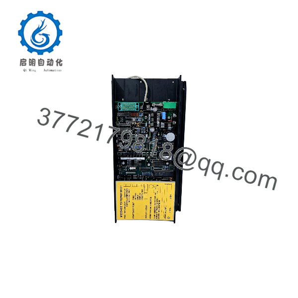
EPC-400 3183050104
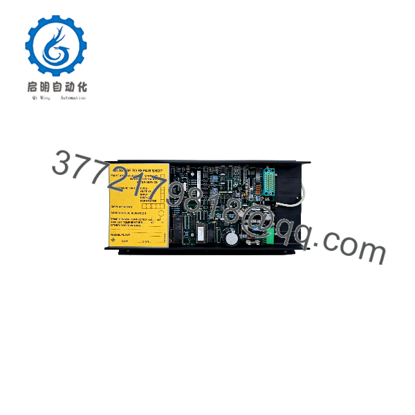
EPC-400 3183050104
Engineering Selection Highlights
- Exact Spare Part Identification (
3183050104/31830-5010-4) → Matches the internal hinged dual-board control module assembly inside the EPC-400 cabinet, distinguishing it from the complete EPC-400 cabinet assembly, power transformer (4900795-18), or 3.0 A main circuit breaker (4900860-26). - Dual-Board ALCAP Architecture → Combines sequence/relay control on the front board with dedicated water-transducer monitoring on the rear board, required for ALCAP purifier systems operating with a water transducer.
- Built-In PI Heater Controller → Eliminates the need for a separate external temperature controller when managing Heatpac electric heaters or fluid-heated preheater valves.
- Multi-Plug Harness Connections → Uses keyed multi-pin plug connectors on the circuit boards so the module can be disconnected and swapped without unlanding individual field wires from the cabinet base terminals (
XA). - Field-Programmable Parameter Memory → Allows technicians to re-enter installation, timer, and process parameters directly from the front panel after module replacement without requiring an external programming laptop.
System Compatibility & Integration Requirements
| Item / Dependency | Verified Compatibility or Requirement | Practical Note |
| Parent Control Cabinet | Alfa Laval EPC-400 Control Unit | Mounts inside the existing EPC-400 enclosure using two retention screws on the hinged frame. |
| Internal Power Supply Hardware | EPC-400 mounting plate with terminals (XA), power line filter (Z1), and transformer (T1) |
Powered from the cabinet’s internal low-voltage secondary windings (10 V / 20 V / 24 V AC taps derived from the 48 V AC control supply). |
| Separator & Process Systems | Alfa Laval ALCAP centrifugal fuel and lube oil separator systems | Supports separators equipped with ALCAP water transducers and optional Heatpac or valve-controlled heaters. |
| Front Panel Schematic Overlays | Upper alarm schematic label and lower active-output schematic label | Transfer or verify the plant-specific schematic overlay strips on the front panel so LED indicators match the installed valve/alarm layout. |
| Parameter Backup Requirement | Existing installation (20–49), timer (50–89), and process parameter list |
A replacement module requires manual entry of site-specific separator parameters before returning the purifier to automatic operation. |
Dimensions, Mounting & Connection Notes
- Mechanical Mounting: The control module is mounted on an aluminum frame hinged inside the EPC-400 cabinet and secured in its operating position by two screws. Loosening these two screws allows the module to swing outward for access to the rear circuit board and behind-panel terminals.
- Replacement Procedure: Before removing an existing
3183050104module, record all active parameter settings from the display. Switch off external power to the EPC-400 at the starter main switch, unlock and swing open the front panel door, unplug the wire terminal multi-plugs by hand, and remove the two mounting screws. - Board-Mounted Fuses: Protective fuses are installed directly on both the front circuit board (
A1) and the rear circuit board (A2), in addition to the power-terminal fuses (F12,F13) and the main switch/fuse (F11) inside the cabinet. - Environmental Limits: The host EPC-400 control unit is rated for a maximum ambient operating temperature of 55 °C.
FAQ
What is the Alfa Laval 3183050104? Part number 3183050104 (also written 31830-5010-4) is the replaceable dual-board electronic control module assembly used inside the Alfa Laval EPC-400 centrifugal separator control unit.
Is part number 3183050104 the complete EPC-400 cabinet or just the internal module? It is the internal control module assembly—comprising the front and rear circuit boards on a hinged aluminum frame—rather than the complete outer cabinet, transformer, and terminal baseplate.
What systems use the EPC-400 control module? The EPC-400 is used on Alfa Laval ALCAP separation systems to automate separator startup, oil purification, water-transducer monitoring, sludge discharge, preheater temperature control, and shutdown sequences.
Do parameters need to be programmed after installing a replacement 3183050104 module? Yes. Before removing the faulty module, technicians must record all existing process, installation (20–49), and timer (50–89) parameter values and re-enter them on the replacement module using the front push-buttons with the mode selector set to P.
How is the 3183050104 control module wired to the separator system? All input and output connections between the control module and the cabinet terminal plate (XA) use multi-pin plug connectors that attach directly to sockets on the module’s circuit boards.
Verification & Troubleshooting Notes
- Blank Display / No Power to Module: Check power-terminal fuses
F12andF13as well as the main switch/circuit breaker (F11) and incoming 48 V AC supply to transformerT1. - Loss of Rear Board / Water-Transducer Function: Inspect fuse
F2on the rear circuit board (A2), which protects the 10 V AC supply feeding boardA1-4. When restarting after replacing a fuse, cycle powerON–OFF–ONas specified in the EPC-400 service procedure. - LED & Display Self-Test: Press and hold the alarm reset push-button for 5 seconds to trigger the built-in lamp test and verify that all front-panel LEDs illuminate properly.
- Persistent Module Faults: Alfa Laval specifies that if a persistent electronic fault is confirmed within the control module itself, the module should not be repaired at the component level onboard; instead, replace the complete
3183050104module after isolating external mains power at the starter panel.