WhatsApp: +86 16626708626
 Email:
 Phone: +86 16626708626
Description
Core Product Summary (Brand / Model / Key Attributes)
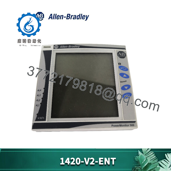
The Allen-Bradley 1420-V2-ENT is a digital power metering unit within the PowerMonitor 500 family, designed for submetering, energy management, and electrical system monitoring in industrial facilities. Operating as an integrated compact monitoring device, it measures core three-phase electrical variables including line-to-line and line-to-neutral voltages, phase currents, active power, reactive power, apparent power, power factor, and total energy consumption using true RMS calculation methods.
Equipped with a 10/100 Mbps Ethernet communication port, the 1420-V2-ENT supports EtherNet/IP, Modbus TCP/IP, and HTTP web server protocols for real-time integration into ControlLogix, CompactLogix, and plant-wide supervisory control and data acquisition systems. The unit accepts direct voltage inputs up to 600V AC line-to-line (400V AC line-to-neutral) and measures current via external 5A nominal current transformers. Featuring a standard 96×96 mm DIN panel footprint with an IP65/NEMA 4X front display, it includes configurable alarm logic and dual output capabilities for facility power quality analysis and automated load monitoring.
Key Technical Specifications
| Specification Parameter | Verified Value / Range |
|---|---|
| Product Family | PowerMonitor 500 |
| Catalog / Order Number | 1420-V2-ENT |
| Measurement Method | True RMS sampling (3840 samples/s at 60 Hz, 3200 samples/s at 50 Hz) |
| Nominal Direct Voltage Input | Up to 600V AC Line-to-Line (400V AC Line-to-Neutral) |
| Voltage Input Range | 277 to 830V AC Line-to-Line RMS / 160 to 480V AC Line-to-Neutral RMS |
| Nominal Current Input | 5 A nominal (6 A maximum continuous via external CTs) |
| System Wiring Configurations | 1-phase, 2-phase, or 3-phase systems |
| Auxiliary Control Power | 100 to 240V AC (48 to 62 Hz) / 120 to 240V DC |
| Communication Ports | 1x 10/100 Mbps Ethernet (RJ45 connector) |
| Industrial Network Protocols | EtherNet/IP, Modbus TCP/IP, HTTP |
| Output Types | Dual SPDT relay outputs / Pulse output (retransmission) |
| Front Display Type | 4-row, 4-digit LED display |
| Front Panel Protection Rating | IP65, NEMA 4X, NEMA 12 |
| Enclosure Dimensions (W x H x D) | 96 x 96 x 50 mm (3.78 x 3.78 x 1.97 in.) |
| Operating Temperature Range | -25°C to +40°C (-13°F to +104°F) |
Detailed Product Overview
The Allen-Bradley 1420-V2-ENT PowerMonitor 500 functions as a panel-mounted electrical submeter designed to aggregate key power data across industrial low-voltage and medium-voltage distribution networks. By continuously sampling voltage and current waveforms using true RMS measurement techniques, the device accurately captures non-linear electrical loads, variable frequency drive outputs, and distorted system harmonics. It presents primary electrical values locally via a multi-row 4-digit LED display while simultaneously serving live data across industrial Ethernet networks.
In control network topologies, the integrated Ethernet interface enables direct communications with Allen-Bradley Programmable Automation Controllers (PACs) via native EtherNet/IP Implicit and Explicit messaging, eliminating the need for dedicated serial gateways or protocol converters. Support for Modbus TCP/IP allows secondary communication with third-party building management systems (BMS) or enterprise energy management software. System operators can leverage the unit’s onboard digital outputs to trigger discrete hardware interlocks or alarms when voltage drops, current overloads, or poor power factor conditions exceed preconfigured setpoints.
The hardware construction utilizes a standard 96×96 mm DIN cut-out profile, facilitating straightforward installation into control cabinet doors, motor control center (MCC) buckets, and switchgear enclosures. Screw-clamp terminal blocks on the rear panel accommodate input wiring from potential transformers (PTs/VTs) and 5A secondary current transformers (CTs), enabling field adaptation to diverse power system topologies without altering internal meter hardware.
1420-V2-ENT
Engineering Selection Highlights
- Direct 600V AC Sensing Capacity: Accepts direct line-to-line voltage inputs up to 600V AC without external potential transformers, simplifying cabinet wiring in standard 480V and 600V industrial distribution panels.
- Native Industrial Ethernet Integration: Features built-in EtherNet/IP and Modbus TCP/IP network interfaces to streamline controller tag configuration and telemetry logging over standard Cat5e/Cat6 infrastructure.
- Standardized 96×96 mm Panel Footprint: Fits universal DIN panel cutouts, enabling direct drop-in replacement or panel mounting alongside industrial switchgear instrumentation.
- External 5A Current Transformer Interface: Interfaces with standard 5A secondary CTs to support a wide range of primary load currents across single-phase and three-phase branch circuits.
- Integrated Alarm Relays: Provides built-in SPDT relay outputs to drive local indicator lights, trip interlocks, or send digital inputs to external PLCs when power parameters drift outside safe boundaries.
- NEMA 4X / IP65 Front Face Rating: Sealed front panel construction protects internal electronics from washdown moisture and dust intrusion when installed on enclosure doors.
System Compatibility & Integration Requirements
| Item / Dependency | Verified Compatibility or Requirement | Practical Note |
|---|---|---|
| Programmable Controllers | Allen-Bradley Logix5000 family (ControlLogix, CompactLogix) | Communicates over EtherNet/IP using standard I/O assembly objects. |
| Network Protocols | EtherNet/IP, Modbus TCP/IP, HTTP Web Server | Supports concurrent network access for PLC control and software data acquisition. |
| Current Transformers | Standard external CTs with 5A AC nominal secondary outputs | CT primary rating must be configured via front panel or network parameters. |
| Terminal Connections | Rear-mounted screw terminal blocks | Accepts maximum 2.5 mm² wire cross-section (recommended torque: 0.5 N·m). |
| Auxiliary Power | 100…240V AC (48…62 Hz) or 120…240V DC | Requires a dedicated control power circuit separate from line voltage inputs. |
Dimensions, Mounting & Connection Notes
- Module Frame Dimensions: Front bezel measures 96 mm (W) x 96 mm (H); overall depth behind the mounting panel is approximately 81.7 mm.
- Mounting Method: Standard flush panel mounting via cutout aperture (96 x 96 mm DIN specification); secured with panel mounting clips.
- Front Panel Protection: Rated IP65, NEMA 4X, and NEMA 12 when properly installed with the included gasket against a flat enclosure surface.
- Wiring Terminal Parameters: Rear screw-type terminals support maximum wire gauges up to 2.5 mm² (14 AWG). Recommended screw tightening torque is 0.5 N·m (0.4 N·m minimum to 0.8 N·m maximum).
- Dielectric & Surge Limits: Impulse withstand voltage rated at 4 kV AC RMS for 1 minute on measuring inputs; surge immunity tested up to 4 kV on current and voltage inputs.
- Operating Ambient Constraints: Operational temperature range covers -25°C to +40°C (-13°F to +104°F) under non-condensing relative humidity levels up to 90%.
FAQ
What is the primary function of the Allen-Bradley 1420-V2-ENT?
The 1420-V2-ENT is a digital power monitoring unit within the PowerMonitor 500 series used to measure, display, and transmit three-phase electrical parameters such as voltage, current, power factor, power, and energy consumption.
Which network protocols are supported by the 1420-V2-ENT Ethernet port?
The integrated 10/100 Mbps Ethernet port natively supports EtherNet/IP, Modbus TCP/IP, and HTTP web interface access.
What are the maximum direct voltage ratings for this unit?
The 1420-V2-ENT supports direct line-to-line inputs up to 600V AC nominal (277 to 830V AC RMS range) and line-to-neutral inputs up to 400V AC nominal (160 to 480V AC RMS range).
How does the 1420-V2-ENT measure system current?
It measures current indirectly using external current transformers (CTs) with a 5A AC nominal secondary output (6A maximum continuous).
What mounting cutout size is required for installation?
The unit fits a standard 96 x 96 mm square DIN panel cutout with panel-clamp hardware securing it from the rear.
What auxiliary supply voltage is required to power the meter?
The internal control power supply requires an auxiliary supply of 100 to 240V AC (48…62 Hz) or 120 to 240V DC.
Verification & Troubleshooting Notes
- Ethernet Link Verification: If Ethernet communications fail to establish with the host controller, verify physical link status via the RJ45 port LEDs and confirm that the assigned IP address, subnet mask, and CIP assembly instances match the controller’s I/O configuration.
- Voltage and Current Phase Matching: Incorrect or negative power readings usually indicate a phase sequence mismatch between voltage sensing terminals and current transformer input pairs. Ensure Phase A CT corresponds strictly to Phase A voltage inputs.
- CT Ratio Configuration: If displayed current or power values do not match actual load readings, check that the configured CT primary-to-secondary ratio programmed in the meter setup menu matches the physical rating of the installed current transformers.
- Display/Power Diagnostics: If the 4-digit LED display fails to illuminate upon powering up, measure the auxiliary power terminals to confirm that control voltage is maintained within the 100–240V AC or 120–240V DC operating window.