
 WhatsApp: +86 16626708626
 Email:
  Phone: +86 16626708626
Description
3. Key Technical Specifications
| Parameter | Value |
|---|---|
| Catalog Number | 1440-TB-H (XM-947) |
| Compatible Modules | XM-160, XM-161, XM-162 (and 1440-VDRS06 / 1440-VDRP06 equivalents) |
| Supply Voltage | 18…32 V DC |
| Current (XM-160 / XM-162) | 190 mA max @ 24 V DC |
| Current (XM-161) | 310 mA max @ 24 V DC |
| Power Dissipation | 4.56 W max (XM-160/162); 7.44 W max (XM-161) @ 24 V DC |
| Operating Temperature | –20…+65 °C (–4…+149 °F) |
| Storage Temperature | –40…+85 °C (–40…+185 °F) |
| Relative Humidity | 95 % non-condensing |
| Dimensions (H × W × D) | 97 × 94 × 94 mm (3.8 × 3.7 × 3.7 in.) |
| Weight | Approx. 0.172 kg (0.38 lb) |
| Mounting | 35 mm DIN rail or panel |
| Terminal Type | Screw clamp |
| Terminal Screw Torque | 0.6–0.8 N·m (5–7 lb·in) |
| Side Connector | Passes primary power (3 A max) and DeviceNet (300 mA max) |
| Conformal Coating | Yes (IPC-A-610C) |
| Hazardous Location | Class I, Div 2, Groups A–D; ATEX Zone 2; Temp Code T4 |
4. Product Introduction
The Allen-Bradley 1440-TB-H is the dedicated screw-clamp terminal base for XM Series overall vibration modules (XM-160, XM-161, XM-162). It provides all field wiring terminations, 24 V DC power distribution, and the side-bus interconnection that lets adjacent XM modules share power and DeviceNet signals.
Engineers specify this base when replacing or expanding vibration monitoring on rotating equipment. The keyed connector and fixed terminal layout prevent module mismatch, while the conformal coating and Class I Div 2 rating keep it serviceable in typical plant environments.
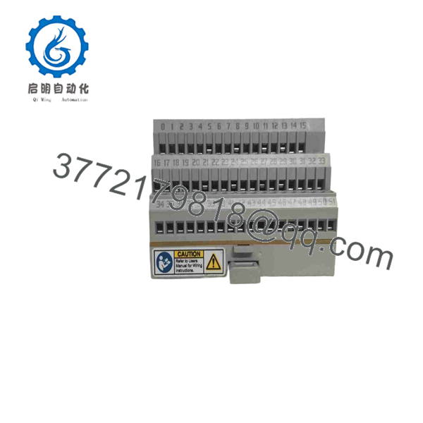
1440-TB-H
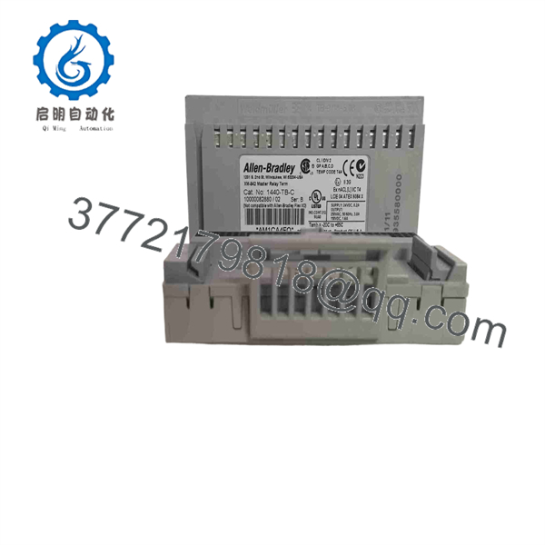
1440-TB-H
5. Troubleshooting Quick Reference
| Symptom | Possible Cause | Relevance to this Part | Quick Check Method | Recommendation |
|---|---|---|---|---|
| No power LEDs on module | Open supply or blown fuse | ❌ Low | Measure 18–32 V DC at base terminals 0/1 or 3/4 | Verify PSU and wiring before swapping base |
| Module will not seat / key mismatch | Wrong terminal base | ✅ High | Confirm keyswitch position matches XM-16x module | Use only 1440-TB-H; other bases will not fit |
| DeviceNet or XM-bus faults on adjacent modules | Side connector damage or poor seating | ✅ High | Inspect side pins for bent/broken contacts; reseat modules | Replace base if pins are damaged |
| Intermittent vibration readings | Loose field wiring or high resistance | ✅ Medium | Torque terminals to 0.6–0.8 N·m; check continuity | Retighten or re-terminate; verify shield grounding |
| Excessive heat or thermal shutdown | Over-current or poor ventilation | ✅ Medium | Measure actual current draw vs. 190/310 mA rating | Confirm total bus load stays under 3 A |
| Communication timeout after swap | Firmware or node-address mismatch | ❌ Low | Read diagnostic buffer in XM software | Issue is almost always module or network, not base |
If the module still faults after these checks, send clear photos of the terminal wiring, side connector, and diagnostic buffer export to technical support.
6. Frequently Asked Questions (FAQ)
Q: Which modules fit the 1440-TB-H?
A: Only the XM-160, XM-161, and XM-162 overall vibration modules (and the corresponding 1440-VDRS06 / 1440-VDRP06 catalog numbers). Do not attempt to mount any other XM module; the keying and pinout will not match.
Q: Is this base still supported / is the series obsolete?
A: The XM platform is mature. Rockwell still lists the terminal bases and many vibration modules as available through authorized channels, but stock is limited. New-surplus units are the practical way to keep existing systems running.
Q: Can I hot-swap the module on this base?
A: No. Remove power from the base before inserting or removing the module. Hot-swapping risks damaging the 96-pin connector and the XM bus on adjacent units.
Q: Why is a new-surplus 1440-TB-H priced lower than a factory-new unit from Rockwell?
A: These are genuine Allen-Bradley parts that left the factory sealed and have never been installed. They carry full functional testing and a 1-year warranty from the seller, but they are not covered by Rockwell’s original factory warranty.
Q: Do I need to reconfigure anything when I replace just the terminal base?
A: No configuration lives in the base. Photograph the existing wiring and terminal labels before you pull the old base, then mirror the exact same terminations. The module itself retains its node address and parameters.
Q: What is the maximum number of modules I can daisy-chain on the side bus?
A: The side connector can pass up to 3 A of primary power. Calculate the sum of all module currents and leave at least 20 % margin. DeviceNet power is limited to 300 mA total on the bus.
Q: Is conformal coating standard?
A: Yes. All 1440-TB-H units leave the factory with conformal coating on the printed-circuit board per IPC-A-610C.



